6
Troubleshooting and Maintenance
6-4 | CFW-11 RB
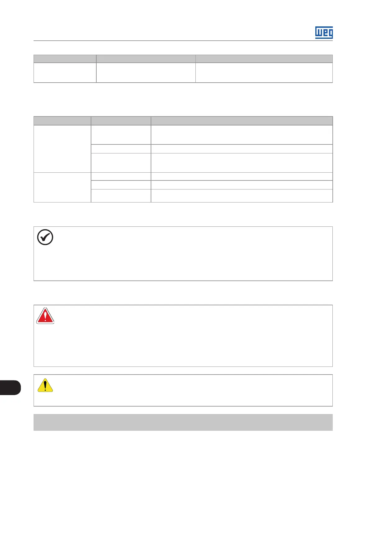
Fault/Alarm Description Possible Causes
F183
IGBT Overload +
Temperature.
Overtemperature related to the IGBTs
overload protection.
Surrounding air temperature too high.
Operation with overload.
6.3 SOLUTIONS FOR THE MOST FREQUENT PROBLEMS
Table 6.2: Solutions for the most frequent problems
Problem Point to be Verified Corrective Action
DC Link does not reach
the value set in P0151
Incorrect wiring
connection
1. Check all power and control connections. For instance, the digital inputs set to
start/stop, general enable, or no external fault shall be connected to the 24 Vdc or
to DGND* terminals (refer to Figure 3.25 on page 3-31)
Incorrect settings
1. Check if parameters are properly set for the application
Fault
1. Check if the converter is not blocked due to a fault condition
2. Check if terminals XC1:13 and XC1:11 are not shorted (short-circuit at the 24 Vdc
power supply)
Off display Keypad connections
1. Check the external keypad connections
Open power supply fuse(s)
1. Replace fuses
24 Vdc power supply
voltage
1. Check if the 24 Vds control voltage is proper connected and turned on
6.4 INFORMATION FOR CONTACTING TECHNICAL SUPPORT
NOTE!
For technical support and servicing, it is important to have the following information in hand:
Converter model.
Serial number, manufacturing date, and hardware revision that are listed in the product nameplate
(refer to Section 2.5 CFW-11 RB MODEL SPECIFICATION (SMART CODE) on page 2-12).
Installed software version (check parameter P0023).
Application data and converter settings.
6.5 PREVENTIVE MAINTENANCE
DANGER!
Always turn off the mains power supply before touching any electrical component associated to
the converter.
High voltage may still be present even after disconnecting the power supply.
To prevent electric shock, wait at least 10 minutes after turning off the input power for the complete
discharge of the power capacitors.
Always connect the equipment frame to the protective ground (PE). Use the adequate connection
terminal in the converter.
ATTENTION!
The electronic boards have electrostatic discharge sensitive components.
Do not touch the components or connectors directly. If needed, first touch the grounded metallic frame
or wear a ground strap.
Do not execute any applied potential test on the CFW11 RB!
If needed, consult WEG.
The converter require low maintenance when properly installed and operated. Table 6.3 on page 6-5 presents
main procedures and time intervals for preventive maintenance. Table 6.4 on page 6-5 provides recommended
periodic inspections to be performed every 6 months after converter start-up.