3
Installation and Connection
CFW-11 RB | 3-17
KA1
K1KA2
21
NF
K(PCR)
K1
A
B
C
R
S
T
Converter
CF W-11 RB
Input
filter
Synchronism
Pre-charge
DC+
DC-
R
R
R
RT1
Stop
220 VAC
external
S
OFF
S
ON
KA1
KA1
KA2
XC1:23
DO1-CC11
PCR
NA
C22
KA2
KA2
K(PCR)
K(PCR)
RT1
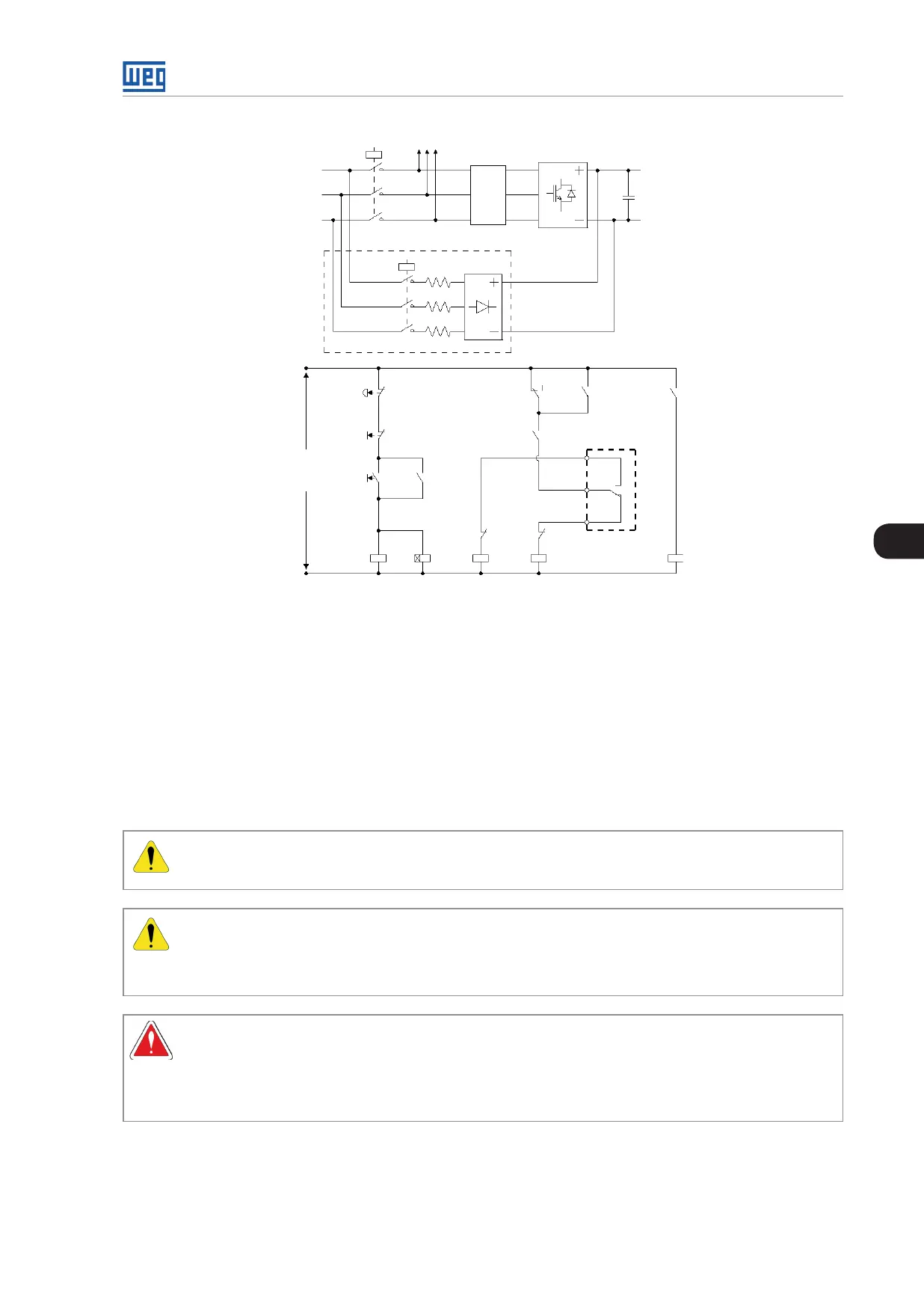
Figure 3.18: Pre-charge circuit example
A contactor or a motorized circuit breaker can be installed at the input of the CFW-11 RB (represented by K1)
and its command must be interlocked with the pre-charge contactor K(PCR) command. Figure 3.18 on page
3-17 presents an example of the recommended pre-charge circuit for the CFW-11 RB converter with simplified
power and command diagrams. There is already a digital output (D01) configured as “Pre-charge OK” function
in the CC11 RB board. This digital output must be used to command the pre-charge contactor and the main
contactor (motorized circuit breaker). Furthermore, the pre-charge timing must be set for the protection of the
auxiliary circuit (resistors, rectifier bridge). This function is carried out by a timer relay with a normally-closed
on-delay contact, represented as RT1 in the figure Figure 3.18 on page 3-17.
3.2.3 Power/Grounding Wiring and Fuses
ATTENTION!
Use proper cable lugs for the power and grounding connection cables.
ATTENTION!
Sensitive equipment such as PLCs, temperature controllers, and thermal couples shall be kept at
a minimum distance of 0.25 m (9.84 in) from the converter and from the cables that connect the
converter to the motor.
DANGER!
Wrong cable connection:
Check all the connections before powering up the converter.
When replacing an existing converter by a CFW-11 RB, check if the installation and wiring is according
to the instructions listed in this manual.