3
Installation and Connection
3-34 | CFW-11 RB
General
Enable
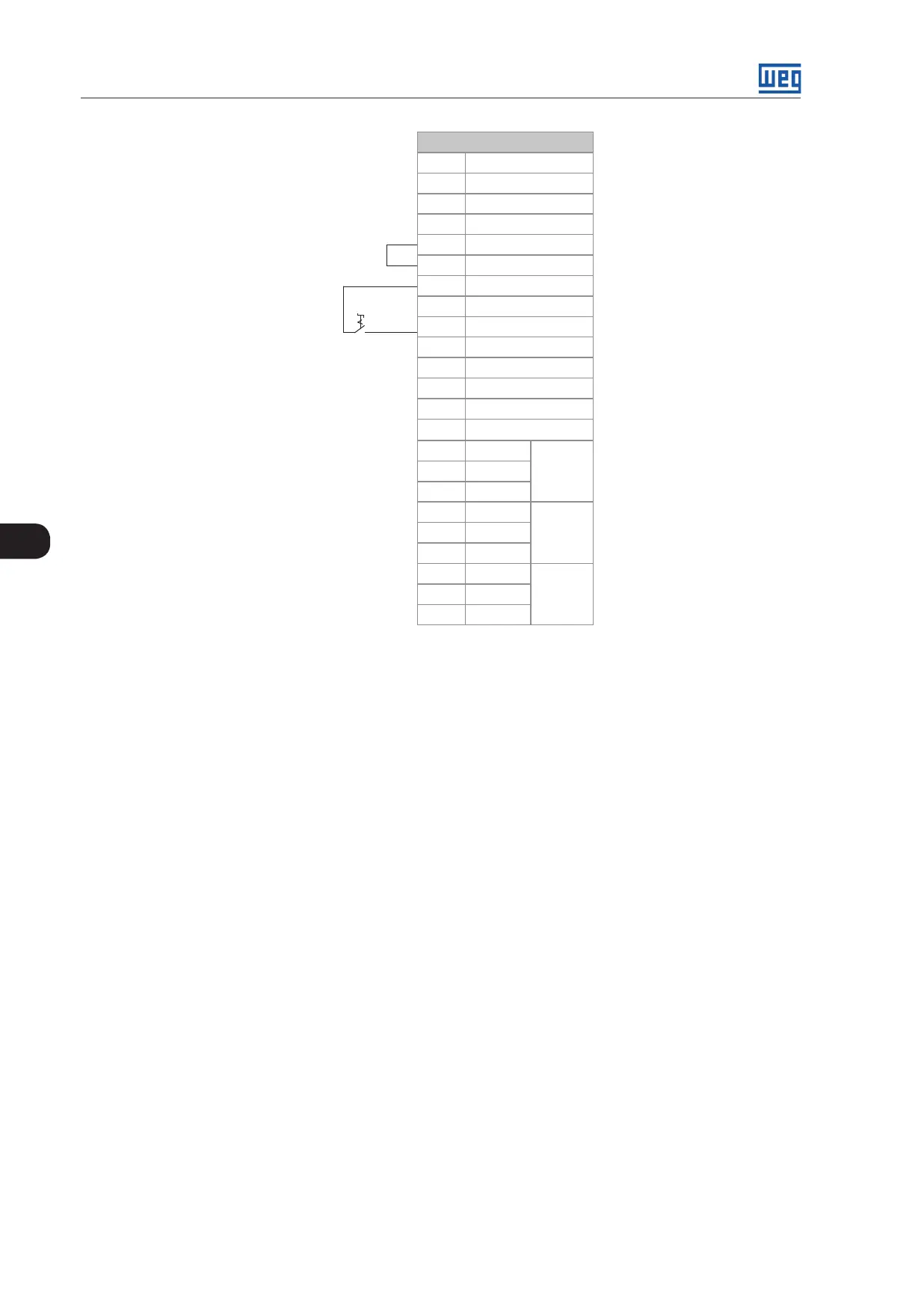
XC1 Connector
7 AO1
8 AGND (24 V)
9 AO2
10 AGND (24 V)
11 DGND
(*)
12 COM
13 24 Vcc
14 COM
15 DI1
16 DI2
17 DI3
18 DI4
19 DI5
20 DI6
21 NF1
DO1
(RL1)
22 C1
23 NA1
24 NF2
DO2
(RL2)
25 C2
26 NA2
27 NF3
DO3
(RL3)
28 C3
29 NA3
Figure 3.29: XC1 wiring for control connection 1
3.3 INSTALLATION ACCORDING TO THE EUROPEAN DIRECTIVE OF
ELECTROMAGNETIC COMPATIBILITY
The CFW-11 RB converters, when properly installed, meet the requirements of the electromagnetic compatibility
directive “EMC Directive 2004 / 108 / EC”.
3.3.1 Conformal Installation
For the conformal installation use:
1. Input filter and RFI in order to comply with the conducted emission levels C3 categorie.
2. Shielded control cables, keeping them separate from the other cables as described at Item 3.2.8 Control
Connections on page 3-30.
3. Converter grounding according to the instructions at Item 3.2.5 Grounding Connections on page 3-26.
4. Instruction for conformal installations applicable to converters controlling motors.
 Loading...