3
Installation and Connection
3-28 | CFW-11 RB
L
BOOST
Lf
U
V W
R
W
R
V
R
U
C
U
C
V
C
W
A
B
C
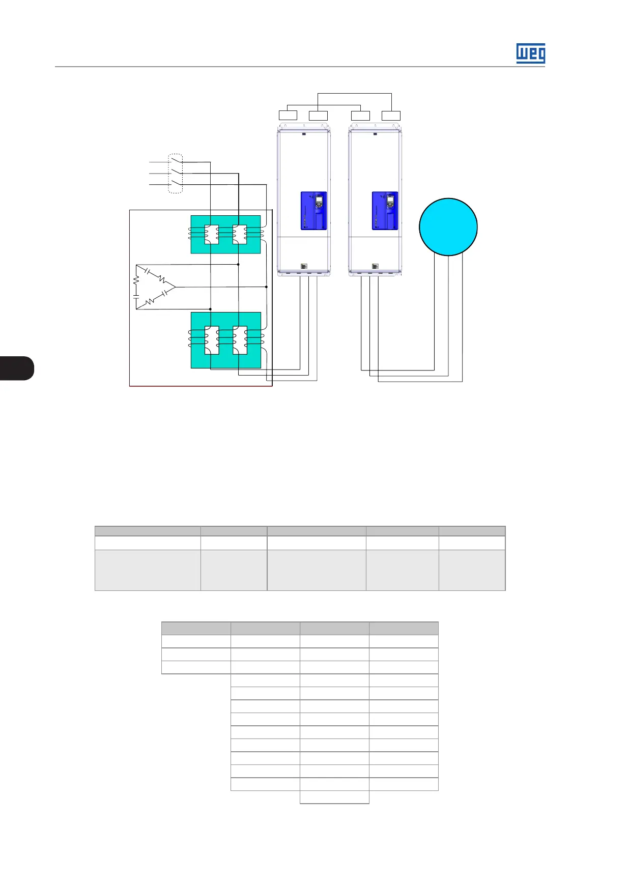
Low voltage power supply
Filter
Inversor
U V
W
Inverter
Motor
Regenerative converter
DC-
DC+
DC- DC+
Figure 3.23: Simplified connection drawing of the filter 2
3.2.6.2 How to Specify the Filter Model
WEG has input filters ready to be used with each of its regenerative converters. In order to specify the input filter
model, replace the voltage and current values in the respective rated supply voltage and rated input current fields
of the smart code as in the example of Table 3.7 on page 3-28.
Table 3.7: Smart code of the input filters
Exemplo WLCL 0242 T 4
Field denomination LCL WEG Filter Filter rated current Number of phases Rated voltage
Possible options Check Table 3.8 on page
3-28
T= three-phase 2 = 220...230V
4 = 380...480V
5 = 500...600V
6 = 660...690V
Table 3.8: Rated currents of the input filters
220...230 V 380...480 V 500...600 V 660...690 V
0142 = 142 A 0105 = 105 A 0053 = 53 A 0046 = 46 A
0180 = 180 A 0142 = 142 A 0063 = 63 A 0054 = 54 A
0211 = 211 A 0180 = 180 A 0080 = 80 A 0073 = 73 A
0211 = 211 A 0107 = 107 A 0100 = 100 A
0242 = 242 A 0125 = 125 A 0108 = 108 A
0312 = 312 A 0150 = 150 A 0130 = 130 A
0370 = 370 A 0170 = 170 A 0147 = 147 A
0477 = 477 A 0216 = 216 A 0195 = 195 A
0515 = 515 A 0289 = 289 A 0259 = 259 A
0601 = 601 A 0315 = 315 A 0312 = 312 A
0720 = 720 A 0365 = 365 A 0365 = 365 A
0760 = 760 A 0435 = 435 A 0427 = 427 A
0472 = 472 A