3
Installation and Connection
3-30 | CFW-11 RB
3.2.8 Control Connections
The control connections (analog inputs/outputs, and digital inputs/outputs) must be made at the electronic control
board CC11 RB terminal strip XC1.
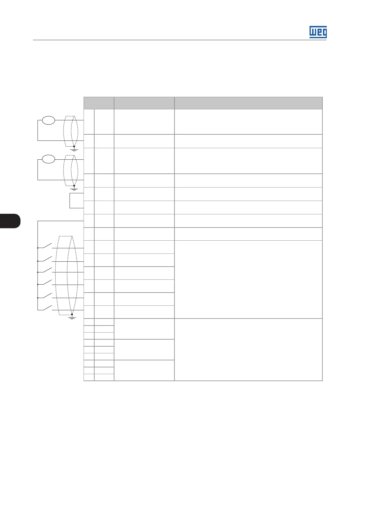
Functions and typical connections are presented at Figure 3.25 on page 3-31.
XC1
Connector
Factory Default
Function
Specifications
7 AO1 Analog output 1:
DC Link voltage
Galvanic Isolation
Resolution: 11 bits
Signal: 0 to 10 V (R
L
≥ 10 kΩ) / 0 to 20 mA / 4 to 20 mA (R
L
≤ 500 Ω)
Protected against short-circuit
8 AGND
(24 V)
Reference (0 V) for the
analog outputs
Connected to the ground (frame) through impedance: 940 Ω resistor
in parallel with a 22 nF capacitor
9 AO2 Analog output 2:
AC Current
Galvanic Isolation
Resolution: 11 bits
Signal: 0 to 10 V (R
L
≥ 10 kΩ) / 0 to 20 mA / 4 to 20 mA (R
L
≤ 500 Ω)
Protected against short-circuit
10 AGND
(24 V)
Reference (0 V) for the
analog outputs
Connected to the ground (frame) through impedance: 940 Ω resistor
in parallel with a 22 nF capacitor
11 DGND* 24 Vdc power supply Connected to the ground (frame) through impedance: 940 Ω resistor
in parallel with a 22 nF capacitor
12 COM Digital inputs common
point connection
13 24 Vcc 24 Vdc power supply 24 Vdc power supply, ±8 %
Capacity: 500 mA
14 COM Digital inputs common
point connection
15 DI1 Digital input 1:
General enable
6 isolated digital inputs
High level ≥ 18 V
Low level ≤ 3 V
Maximum input voltage = 30 V
Input current: 11 mA @ 24 Vdc
16 DI2 Digital input 2:
No function
17 DI3 Digital input 3:
No function
18 DI4 Digital input 4:
No function
19 DI5 Digital input 5:
No function
20 DI6 Digital input 6:
No function
21 NF1 Digital output 1 DO1
(RL1): Pre-charge OK
Contact rating:
Maximum voltage: 240 Vac
Maximum current: 1 A
NC - normally closed contact
C - common
NO - normally open contact
22 C1
23 NA1
24 NF2 Digital output 2 DO2
(RL2): RUN
25 C2
26 NA2
27 NF3 Digital output 3 DO3 (RL3):
No fault
28 C3
29 NA3
volt
amp
a) Digital inputs as active high