3
Installation and Connection
3-12 | CFW-11 RB
3.2 ELECTRICAL INSTALLATION
DANGER!
The following information is merely a guide for proper installation. Comply with applicable local
regulations for electrical installations.
DANGER!
Make sure the AC power supply is disconnected before starting the installation.
ATTENTION!
Integral solid state short circuit protection does not provide branch circuit protection. Branch circuit
protection must be provided in accordance with applicable local standards.
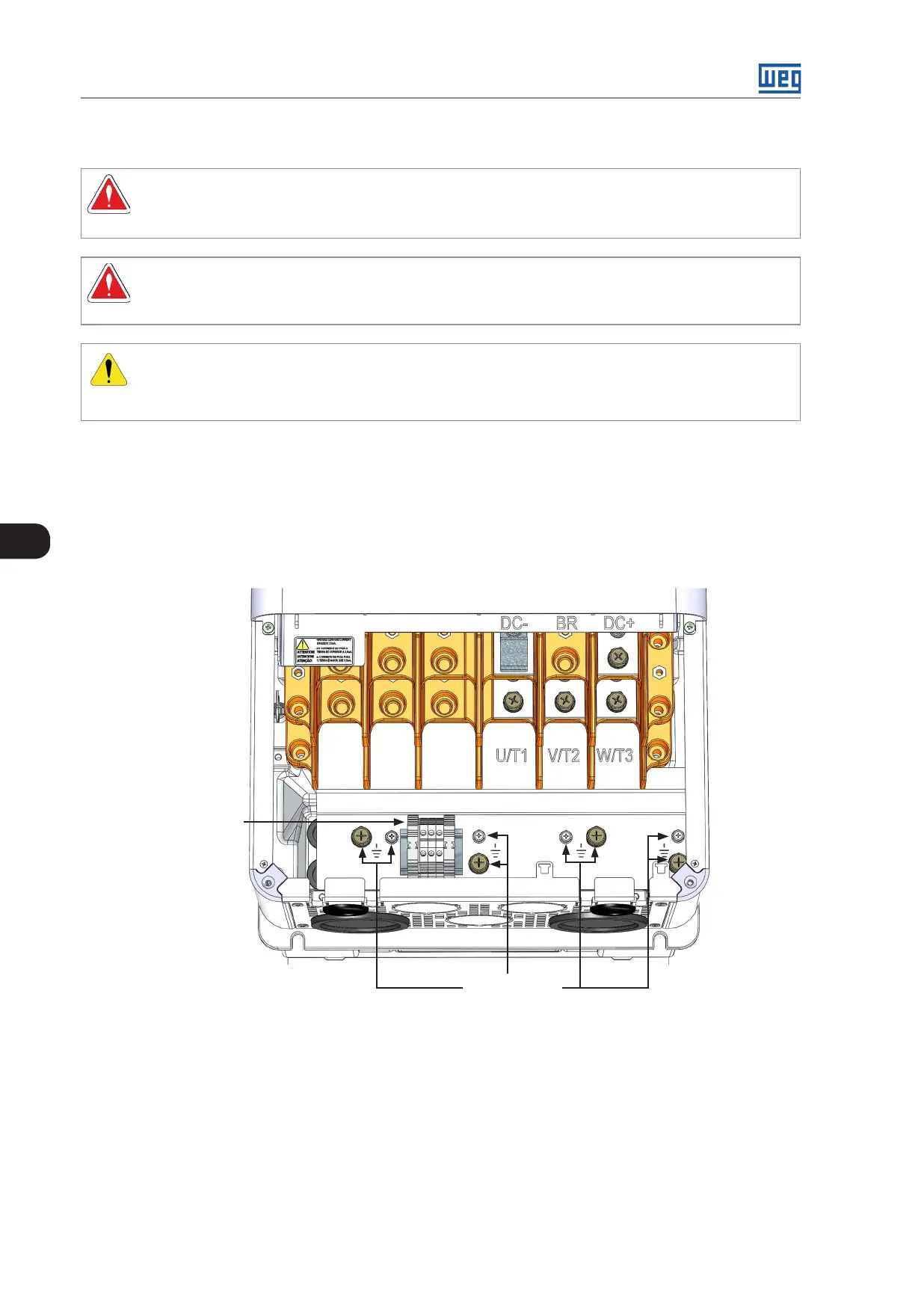
3.2.1 Identification of the Power and Grounding Terminals
U/T1, V/T2, W/T3: AC power supply.
DC-: this is the negative potential terminal in the DC Link circuit.
DC+: this is the positive potential terminal in the DC Link circuit.
Synchronism
terminal
Grounding
(4 x M8, 4 x M5)
Figure 3.14: Grounding, synchronism and power terminals of frame size E models
 Loading...