3
Installation and Connection
CFW-11 RB | 3-33
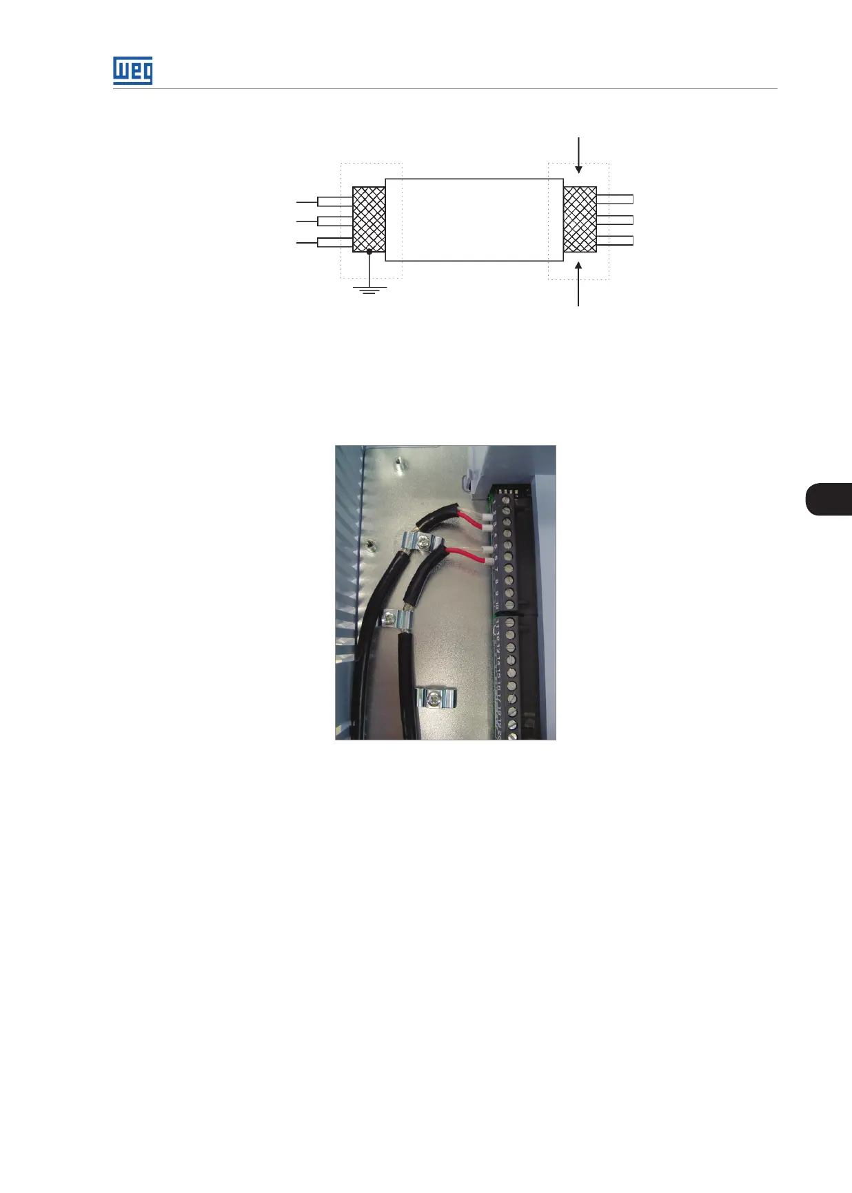
Do not ground
Converter
side
Isolate with tape
Figure 3.27: Shield connection
5. Relays, contactors, solenoids or coils of electromechanical brakes installed close to the converter may eventually
create interferences in the control circuit. To eliminate this effect, RC suppressors (with AC power supply) or free-
wheel diodes (with DC power supply) shall be connected in parallel to the coils of these devices.
Figure 3.28: Example of shield connection for the control wiring and synchronism
3.2.9 Typical Control Connection
Control connection 1 - Control via Keypad (HMI) with General Enable function.
The factory default settings allows the converter to operate in local mode. This operation mode is recommended
for first-time users due to its easiness of implementation.
For the start-up in this operation mode, please follow instructions listed in Chapter 5 FIRST TIME POWER-UP
AND START-UP on page 5-1.
DI1 is already set to General Enable as factory default (P0263 = 2).
 Loading...