3
Installation and Connection
3-32 | CFW-11 RB
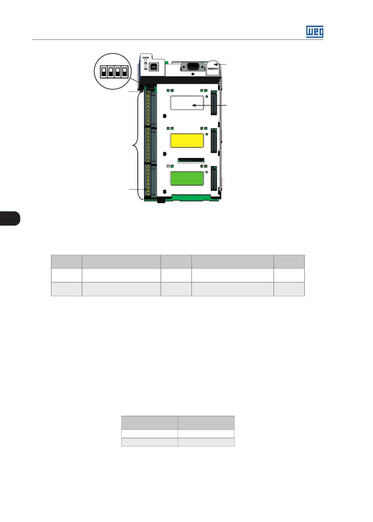
XC1
ON
S1
1 2 3 4
1
29
Slot 1 (white)
Slot 5
Figure 3.26: Connector XC1 and DIP-switches for selecting the signal type of the analog inputs and outputs
The analog inputs and outputs are factory set to operate from 0 to 10 V; this setting may be changed by using
DIP-switch S1.
Table 3.9: DIP-switches configuration for selecting the signal type of the analog outputs
Signal Factory Default Function
DIP-
Switch
Selection
Factory
Setting
AO1 DC Link Voltage S1.1
OFF: 4 to 20 mA / 0 to 20 mA
ON: 0 to 10 V (factory setting)
ON
AO2 Input current S1.2
OFF: 4 to 20 mA / 0 to 20 mA
ON: 0 to 10 V (factory setting)
ON
Parameters related to the analog outputs (AO1 and AO2) shall also be programmed according to the DIP-switches
settings and desired values.
Follow instructions below for the proper installation of the control wiring:
1. Wire gauge: 0.5 mm² (20 AWG) to 1.5 mm
2
(14 AWG).
2. Maximum tightening torque: 0.5 Nm (4.50 lbf.in).
3. Use shielded cables for the XC1 connections and run the cables separated from the remaining circuits (power,
110 V / 220 Vac control, etc.) as presented in Table 3.10 on page 3-32. If control wiring must cross other cables
(power cables for instance), make it cross perpendicular to the wiring and provide a minimum separation of 5 cm
(1.9 in) at the crossing point.
Table 3.10: Minimum separation distances between wiring
Cable Length
Minimum Separation
Distance
≤ 30 m (100 ft) ≥ 10 cm (3.94 in)
> 30 m (100 ft) ≥ 25 cm (9.84 in)
4. The proper connection of the cable shield is shown in Figure 3.27 on page 3-33. Figure 3.28 on page 3-33
shows how to connect the cable shield to the ground.
 Loading...