3
Installation and Connection
CFW-11 RB | 3-15
3.2.2 Pre-charge Circuit
The resistors of the pre-charge circuit must be sized according to the following criteria:
Maximum voltage.
Maximum energy.
Power overload capacity of the resistors during the pre-charge period (energy dissipation capacity).
NOTE!
The pre-charge resistor is sized considering that the CFW-11 RB is feeding a CFW-11 DC inverter
of the same current value.
In case the CFW-11 RB is not feeding an inverter of the same current value, contact WEG.
In case the CFW-11 RB is feeding other converter, WEG must be consulted.
The characteristics of the resistors must be obtained with their manufacturer.
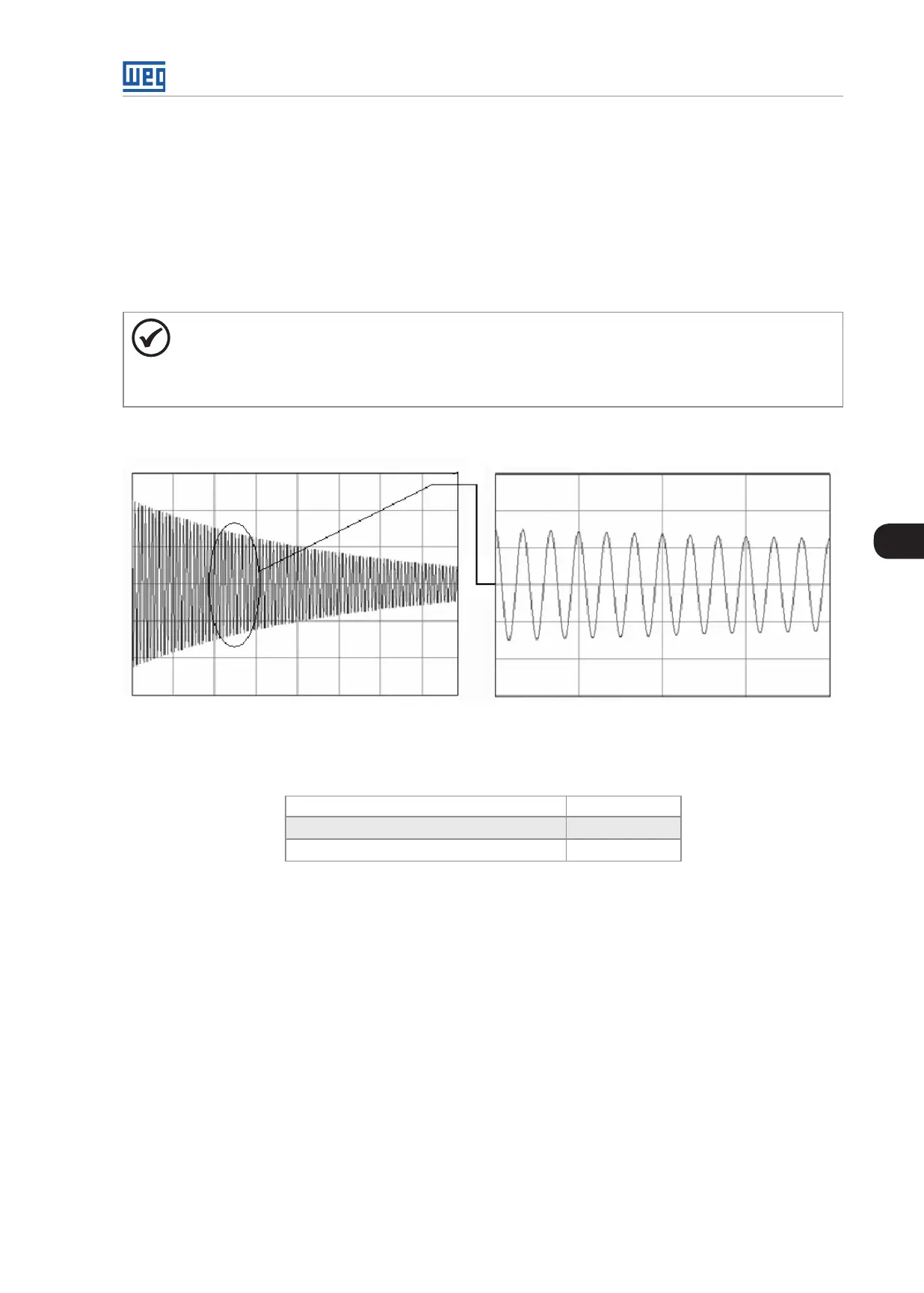
t
0 0,2 0,4 0,6 0,8 1 1,2 1,4 0,4 s 0,6 st
Figure 3.17: Current during the pre-charge
Table 3.2: Sizing of the pre-charge
Peak current during the pre-charge (A) 0,83∙(V
line
/R)
Energy stored in the capacitor bank (J) k
E
∙ V
line
2
Pre-charge duration (s) k
T
∙ R
Where R is the ohmic value of the resistor used for each phase and N is the number of power units.
 Loading...