6
Troubleshooting and Maintenance
CFW-11 RB | 6-3
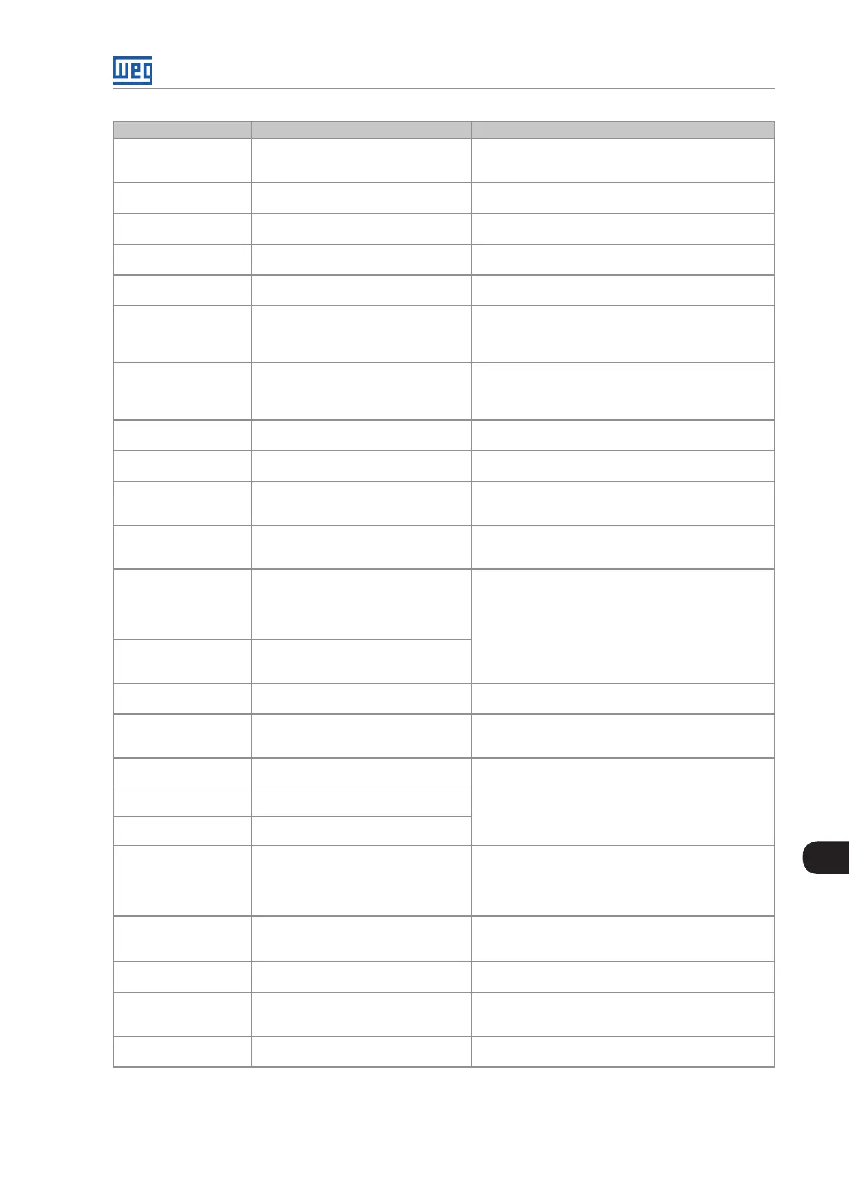
Fault/Alarm Description Possible Causes
F074
Ground Fault
A ground fault occured.
Note:
It may be disabled by setting P0343 = 0.
+UD or -UD short-circuit to ground.
F080
CPU Watchdog
Microcontroller watchdog fault. Electrical noise.
F082
Copy Function Fault
Fault while copying parameters. An attempt to copy the keypad parameters to an converter
with a different firmware version.
F084
Auto-diagnosis Fault
Auto-diagnosis Fault. Defect in the converter internal circuitry.
A088
HMI Communication Lost
Indicates a problem with the keypad and
control board communication.
Loose keypad cable connection.
Electrical noise in the installation.
A090
External Alarm
External alarm via digital input.
Note:
It is required to set a digital input to "No
external alarm".
Wiring was not connected to the digital input (DI1 to DI8)
set to “No external alarm”).
F091
External Fault
External fault via digital input.
Note:
It is required to set a digital input to “No
external fault”.
Wiring was not connected to the digital input (DI1 to DI8)
set to “No external fault”.
F099
Invalid Current Offset
Current measurement circuit is measuring a
wrong value for null current.
Defect in the converter internal circuitry.
F101
Invalid Voltage Offset
Offset calculation error when reading the
input voltage (synchronism).
Main contactor closed before the pre-charge is complete.
CPU has reset and the main contactor did not open.
A105
Reactive Injection in the
Power Supply
Alarm for the reactive current injection in
the power supply.
Voltage power supply much higher than the rated voltage.
P0180 too low.
F151
Flash Memory Module
Fault
Flash Memory Module fault (MMF-01). Defective flash memory module.
Check the connection of the flash memory module.
A152
Internal Air High
Temperature
Alarm indicating that the internal air
temperature is too high.
Note:
It may be disabled by setting P0353 = 1
or 3.
Surrounding air temperature too high (> 40 °C or 50 °C
(104 °F or 122°F) according to the model - refer to Section
3.1 MECHANICAL INSTALLATION on page 3-1) and
excessive output current.
Blocked or defective fan.
Fins of the book heatsink too dirty, impairing the air flow.
F153
Internal Air
Overtemperature
Internal air overtemperature fault.
A155
Undertemperature
Only one sensor indicates temperature
below -30°C.
Surrounding air temperature ≤ -30 °C (-22 °F).
F156
Undertemperature
Undertemperature fault below -30 °C (-22
°F) in the IGBTs or rectifier measured by the
temperature sensors.
Surrounding air temperature ≤ -30 °C (-22 °F).
Defective internal circuitry of the power modules (supply,
cables).
F174
Left Fan Speed Fault
Fault on the heatsink left fan speed. Dirt on the blades and rolling bearings of the fan.
Defective fan.
Defective fan power supply connection.
F175
Center Fan Speed Fault
Fault on the heatsink center fan speed.
F176
Right Fan Speed Fault
Fault on the heatsink right fan speed.
A177
Fan Replacement
Fan replacement alarm (P0045 > 50000
hours).
Note:
This function may be disabled by setting
P0354 = 0.
Maximum number of operating hours for the heatsink fan
has been reached.
A178
Fan Speed Alarm
Alarm on the heatsink fan speed. Dirt on the blades and rolling bearings of the fan.
Defective fan.
Defective fan power supply connection.
F179
Heatsink Fan Speed Fault
Fan speed is under the minimum limit. The fan is dirt or blocked.
A181
Invalid Clock Value.
Invalid clock value alarm. It is necessary to set date and time at parameters P0194
to P0199.
Keypad battery is discharged, defective, or not installed.
F182
Pulse Feedback Fault
Pulse feedback fault. Defective converter internal circuitry.



 To Next Page