Troubleshooting and Maintenance
6
6-2 | CFW-11
Through a digital input: DIx = 20 (P0263 to P0270).
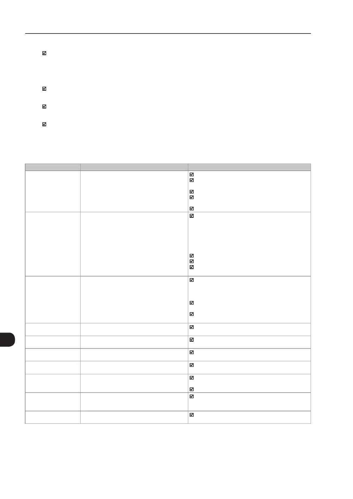
When an alarm situation ("ALARM" (AXXX)) is detected:
The keypad displays the "ALARM" code and description.
The "STATUS" LED changes to yellow.
The PWM pulses are not blocked (the inverter is still operating).
6.2 FAULTS, ALARMS AND POSSIBLE CAUSES
Table 6.1 - Faults, alarms and possible causes
Fault/Alarm Description Possible Causes
F006
Imbalance or
Input Phase Loss
Mains voltage imbalance too high or phase missing
in the input power supply.
Note:
- If the motor is unloaded or operating with reduced
load this fault may not occur.
- Fault delay is set at parameter P0357
P0357 = 0 disables the fault.
Phase missing at the inverter's input power supply.
Input voltage imbalance >5 %.
For the frame size E:
Phase loss at L3/R or L3/S may cause F021 or F185.
Phase loss at L3/T will cause F006.
For frame sizes F and G:
Pre-charge circuit fault.
F021
DC Bus Undervoltage
DC bus undervoltage condition occurred.
The input voltage is too low and the DC bus voltage
dropped below the minimum permitted value (monitor the
value at parameter P0004):
Ud < 530 V - Supply voltage 500 / 525 V (P0296 = 5).
Ud < 580 V - Supply voltage 500 / 575 V (P0296 = 6).
Ud < 605 V - Supply voltage 600 V (P0296 = 7).
Ud < 696 V - Supply voltage 660 / 690 V (P0296 = 8).
Phase loss in the input power supply.
Pre-charge circuit failure.
Parameter P0296 was set to a value above of the power
supply rated voltage.
F022
DC Bus Overvoltage
DC bus overvoltage condition occurred.
The input voltage is too high and the DC bus voltage
surpassed the maximum permitted value:
Ud > 1000 V - For P0296 = 5, 6 or 7.
Ud > 1200 V - For P0296 = 8.
Inertia of the driven-load is too high or deceleration time
is too short.
Wrong settings for parameters P0151, or P0153, or
P0185.
F030
(10)
Power Module U Fault
Desaturation of IGBT occured in Power Module U.
Short-circuit between motor phases U and V or U and W.
F034
(10)
Power Module V Fault
Desaturation of IGBT occured in Power Module V.
Short-circuit between motor phases V and U or V and W.
F038
(10)
Power Module W Fault
Desaturation of IGBT occured in Power Module W.
Short-circuit between motor phases W and U or W and V.
F042
(1)
DB IGBT Fault
Desaturation of Dynamic Braking IGBT occured.
Short-circuit between the connection cables of the
dynamic braking resistor.
A046
High Load on Motor
Load is too high for the used motor.
Note:
It may be disabled by setting P0348 = 0 or 2.
Settings of P0156, P0157, and P0158 are too low for
the used motor.
Motor shaft load is excessive.
A047
IGBTs Overload Alarm
An IGBTs overload alarm occurred.
Note:
It may be disabled by setting P0350 = 0 or 2.
Inverter output current is too high.
F048
IGBTs Overload Fault
An IGBTs overload fault occurred.
Inverter output current is too high.

 Loading...


