Installation and Connection
3
3-14 | CFW-11
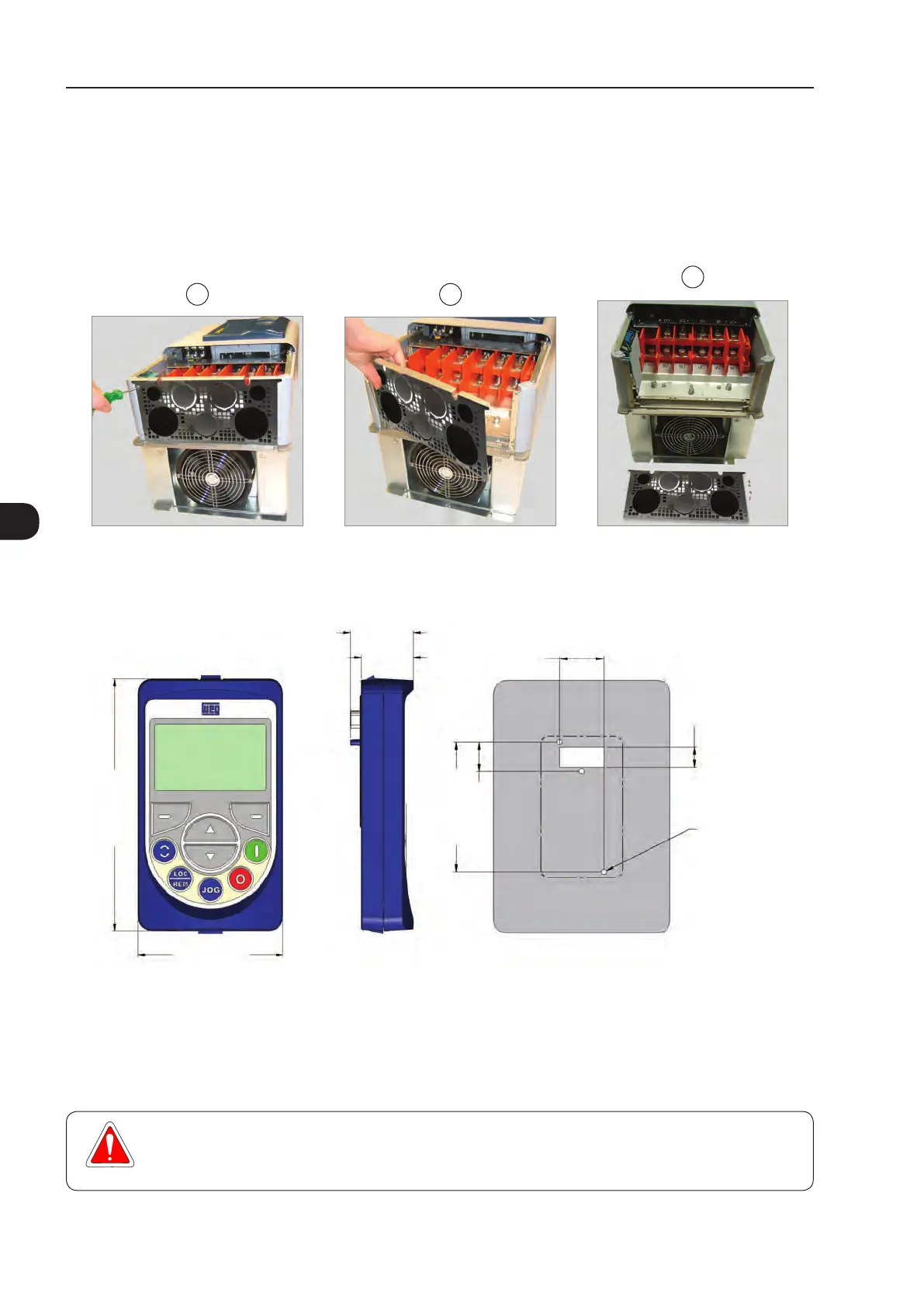
3.1.7 Removal of the Cable Passage Plate - Frame Sizes D and E
When it is not necessary neither IP20 nor Nema1 protection degree, the cable passage plate may be removed
in order to make the inverter electric installation easier. Remove the four M4 screws, according to the procedure
presented in Figure 3.15 on page 3-14.
3
2
1
Figure 3.15 - Removal of the cable passage plate - frame sizes D and E
3.1.8 HMI Installation at the Cabinet Door or Command Panel (Remote HMI)
35.0 [1.38]
28.5 [1.12]
113.0 [4.45]
103.0 [4.06]
23.4 [0.92]
16.0 [0.63]
23.5
[0.93]
65.0 [2.56]
∅4.0 [0.16] (3X)
Figure 3.16 - Data for the HMI installation at the cabinet door or command panel - mm [in]
The keypad frame accessory can also be used to fix the HMI, as mentioned in Table 7.1 on page 7-3.
3.2 ELECTRICAL INSTALLATION
DANGER!
The following information is merely a guide for proper installation. Comply with applicable local
regulations for electrical installations.

 Loading...


