Keypad and Display
4
4-4 | CFW-11
4.2 PARAMETERS ORGANIZATION
When the right soft key ("MENU") is pressed in the monitoring mode, the display shows the first 4 groups of
parameters. An example of how the groups of parameters are organized is presented in Table 4.1 on page
4-4. The number and name of the groups may change depending on the firmware version used. For further
details on the existent groups for the firmware version used, please refer to the software manual.
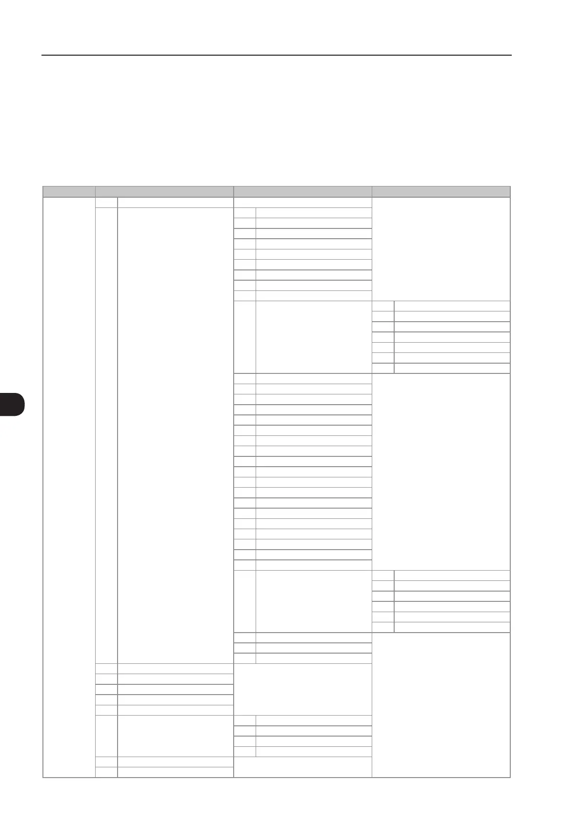
Table 4.1 - Groups of parameters
Level 0 Level 1 Level 2 Level 3
Monitoring 00 ALL PARAMETERS
01 PARAMETER GROUPS 20 Ramps
21 Speed References
22 Speed Limits
23 V/f Control
24 Adjust. V/f Curve
25 VVW Control
26 V/f Current Limit.
27 V/f DC Volt. Limit.
28 Dynamic Braking
29
Vector Control 90 Speed Regulator
91 Current Regulator
92 Flux Regulator
93 I/F Control
94 Self-Tuning
95 Torque Curr. Limit.
96 DC Link Regulator
30 HMI
31 Local Command
32 Remote Command
33 3-Wire Command
34 FWD/REV Run Comm.
35 Zero Speed Logic
36 Multispeed
37
Electr. Potentiom.
38
Analog Inputs
39 Analog Outputs
40 Digital Inputs
41 Digital Outputs
42
Inverter Data
43 Motor Data
44 FlyStart/RideThru
45 Protections
46 PID Regulator
47 DC Braking
48 Skip Speed
49 Communication 110 Local/Rem Config.
111 Status/Commands
112 CANopen/DeviceNet
113 Serial RS-232/485
114 Anybus
115 Profibus DP
50 SoftPLC
51 PLC
52 Trace Function
02 ORIENTED START-UP
03 CHANGED PARAMETERS
04 BASIC APPLICATION
05 SELF-TUNING
06 BACKUP PARAMETERS
07
I/O CONFIGURATION 38 Analog Inputs
39 Analog Outputs
40 Digital Inputs
41 Digital Outputs
08 FAULT HISTORY
09 READ ONLY PARAMS.

 Loading...


