Installation and Connection
3
CFW-11 | 3-41
DANGER!
Le variateur possède une protection thermique réglable pour la résistance de freinage. La résistance
de freinage et le transistor de freinage peuvent être endommagés si les paramètres P0153, P0154 et
P0155 ne sont pas correctement définis ou si la tension d’entrée dépasse la valeur maximale autorisée.
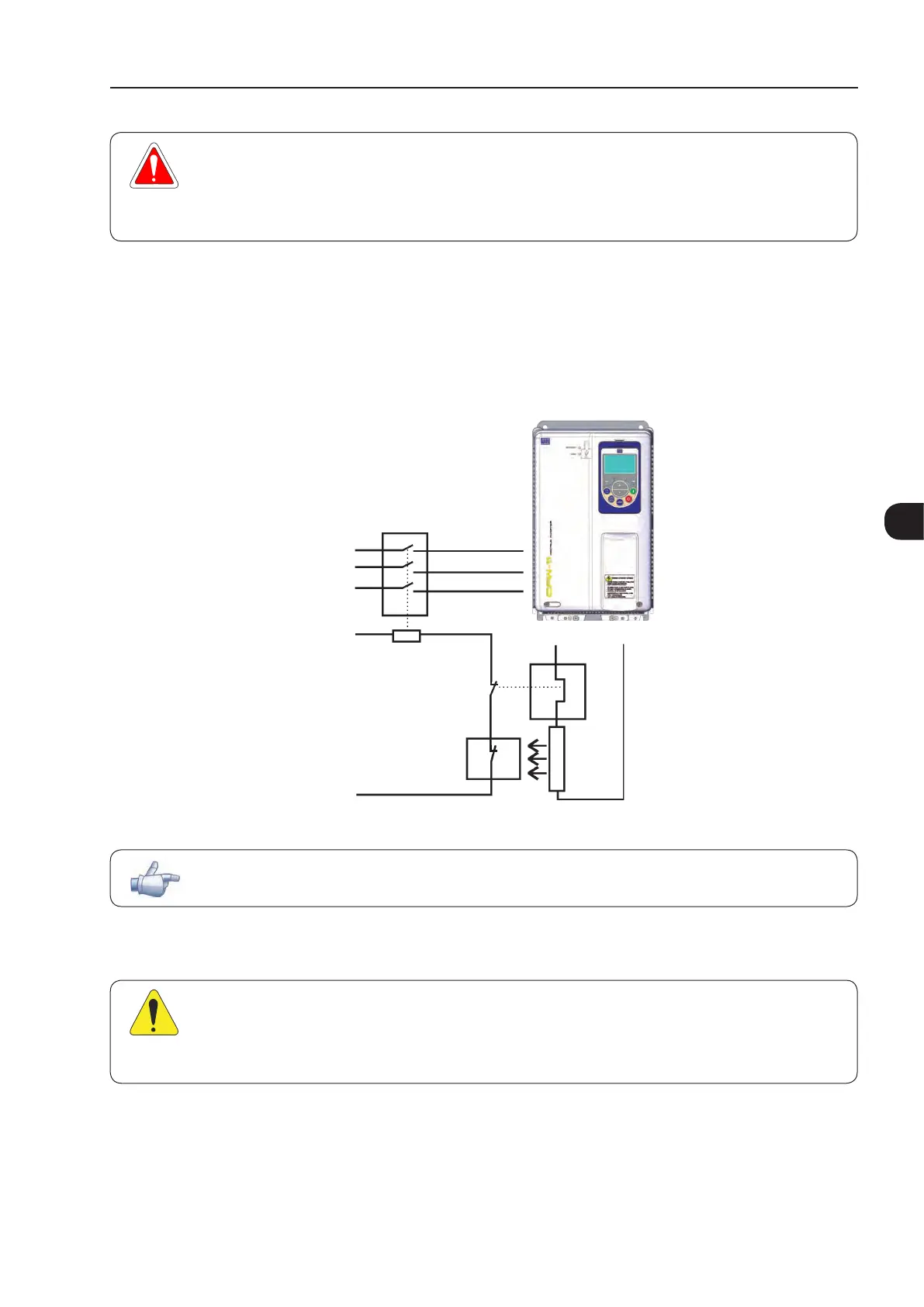
The thermal protection offered by the inverter, when properly set, allows the protection of the resistor in case of
overload; however, this protection is not guaranteed in case of braking circuitry failure. In order to avoid any
damage to the resistor or risk of fire, install a thermal relay in series with the resistor and/or a thermostat in
contact with the resistor body to disconnect the input power supply of the inverter, as presented in Figure 3.32
on page 3-41.
Power
supply
Thermostat
Braking
resistor
Thermal
relay
Control power
supply
Contactor
CFW-11
BR
DC+
R
S
T
Figure 3.32 - Braking resistor connection - frame sizes B, C, D and E
NOTE!
DC current flows through the thermal relay bimetal strip during braking.
3.2.3.3 Output Connections
ATTENTION!
The inverter has an electronic motor overload protection that shall be adjusted according to the
driven motor. When several motors are connected to the same inverter, install individual overload
relays for each motor.

 Loading...


