Installation and Connection
3
CFW-11 | 3-59
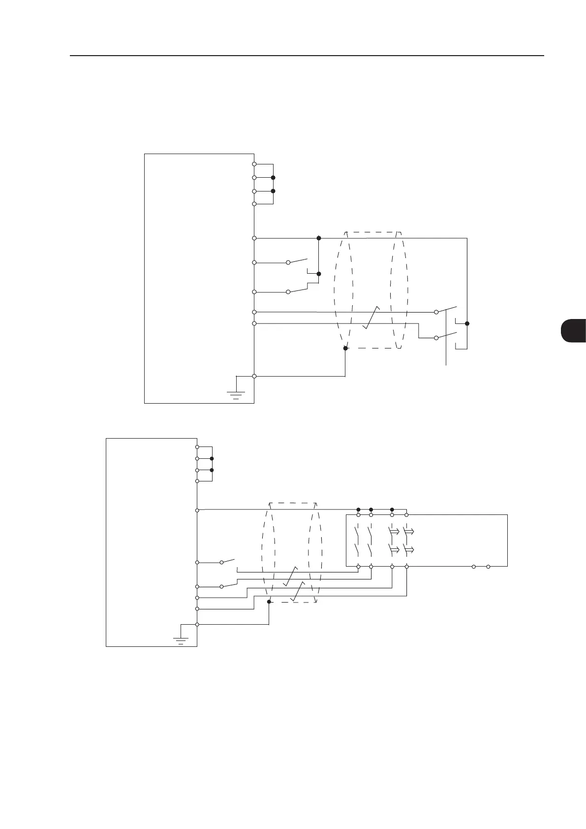
3.3.3 Examples of Wiring Diagrams of Inverter Control Signal
It is recommended to use inverter DI1 and DI2 digital inputs set as 3-wire start/stop commands and the wiring
diagrams of inverter control signal according to Figure 3.46 on page 3-59.
Safety relay
Start
Stop
CFW-11
XC1:1 - DGND*
XC1:12 - COM
XC1:13 - +24 V
XC1:15 - DI1
XC1:16 - DI2
XC25:2 - GND (R1-)
XC25:1 - STO1 (R1+)
XC25:3 - STO2 (R2+)
XC25:4 - GND (R2-)
(a) STO or SS0 safety function (without an external safety relay)
Start
A1 A2
14 24 48 58
13 23 47 57
Stop
CFW-11
XC1:11 - DGND*
XC1:12 - COM
XC1:13 - +24 V
XC1:15 - DI1
XC1:16 - DI2
XC25:2 - GND (R1-)
XC25:1 - STO1 (R1+)
XC25:3 - STO2 (R2+)
XC25:4 - GND (R2-)
External
safety relay
(b) SS1 safety function with an external safety relay
(*)
Note:
(*) For specifications of external safety relay, which is required to realize SS1 (stop category 1), refer to Item 3.3.4 Technical Specifications
on page 3-60.
Figure 3.46 - (a) and (b) - Inverter control wiring examples (XC1 and XC25 terminals) to realize STO (or SS0, i.e., stop category 0)
and SS1 (stop category 1) safety functions according to IEC/EN 61800-5-2 and IEC/EN 60204-1 standards - DI1 and DI2 inputs set
as 3-wire start/stop commands

 Loading...


