129
CFW-08 OPTIONS AND ACCESSORIES
[µH]
L = 1592 x
∆V
x
V
e
f I
S, nom
where:
∆V - desired line voltage drop, in percentage (%);
V
e
- phase voltage at inverter input (line voltage), given in Volts (V);
I
s,nom
- rated inverter output current;
f - line frequency.
L
PE
PE
R
U
V
W
PE
Q1
ST UVW
PE
This practice results in a compromise between motor voltage drop,
power factor improvement and harmonic current distortion
reduction.
Always add a line reactor, when capacitors for power factor correction
are installed in the same line and near to the inverter.
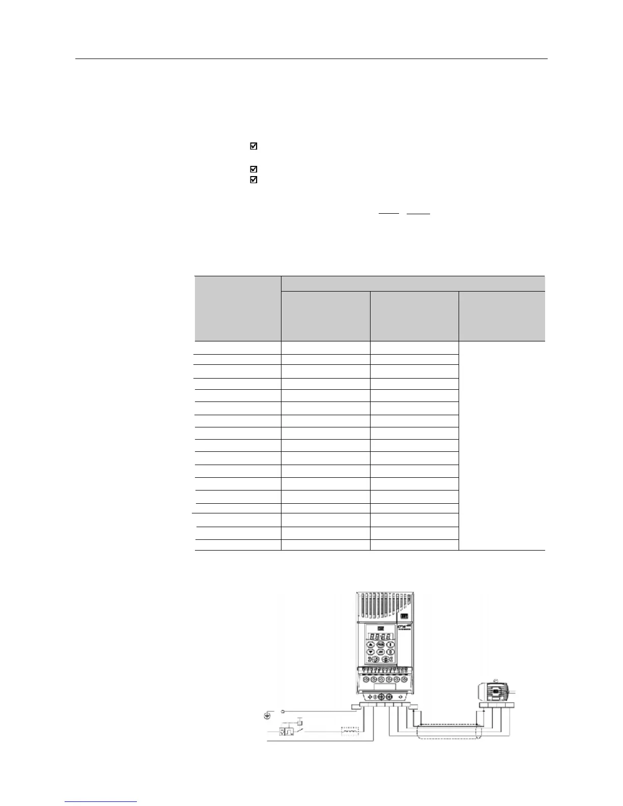
Figure 8.19 shows the line reactor connection to the input.
Use the following equation to calculate the value of the line reactor
necessary to obtain the desired percentage of the voltage drop:
(a) Single-phase power supply models
Line
N
Shield
0.5%
With rated load
at the inverter output
(I
S
= I
S,nom
)
0.25%
0.1%
1.0%
0.5%
1.0%
0.5%
1.0%
0.05%
0.05%
0.1%
0.25%
1.0%
1.0%
0.5%
0.5%
0.5%
1.0%
With 80% of the rated
load at the inverter
output
(I
S
= 0,8I
S,nom
)
0.1%
0.05%
0.5%
0.25%
0.25%
0.25%
0.5%
0.05%
0.05%
0.05%
0.1%
0.5%
0.5%
0.25%
0.25%
0.25%
0.5%
With 50% of the rated
load at the inverter
output
(I
S
= 0,5I
S,nom
)
Minimum Line Impedance
Note: These values ensure a life of 20,000 hour for the DC link capacitors, i.e., they can be operated
during 5 years with operation of 12 hours per day.
Table 8.3 - Minimum network impedance for several load conditions.
Inverter
1.6A / 220-240V
2.6A / 220-240V
4.0A / 220-240V
7.0A / 220-240V
7.3A / 220-240V
10A / 220-240V
16A / 220-240V
1.0A / 380-480V
1.6A / 380-480V
2.6A / 380-480V
2.7A / 380-480V
4.0A / 380-480V
4.3A / 380-480V
6.5A / 380-480V
10A / 380-480V
13A / 380-480V
16A / 380-480V