EasyManuals Logo

WEG CFW08 Vector inverter User Manual

WEG CFW08 Vector inverter
167 pages
To Next Page IconTo Next Page
To Previous Page IconTo Previous Page
Page #55 background imageLoading...
Page #55 background image
54
START-UP
NOTE!
The last frequency reference (speed) vale set via the and
keys is saved.
If you wish to change this value before inverter enabling, change parameter
P121 (Keypad Reference).
NOTES:
(1) If the direction of rotation of the motor is not correct, switch off the
inverter. Wait at least for 10 minutes to allow complete capacitor
discharge and then swap any two wires at the motor output.
(2) If the acceleration current becomes too high, mainly at low frequencies,
set the torque boost (IxR compensation) at P136.
Increase/decrease the content of P136 gadually until you obtain an
operation with constant current over the entire frequency range.
For the case above, refer to Parameter Description in Chapter 6.
(3) If E01 fault occurs during deceleration, increase the deceleration time
at P101 / P103.
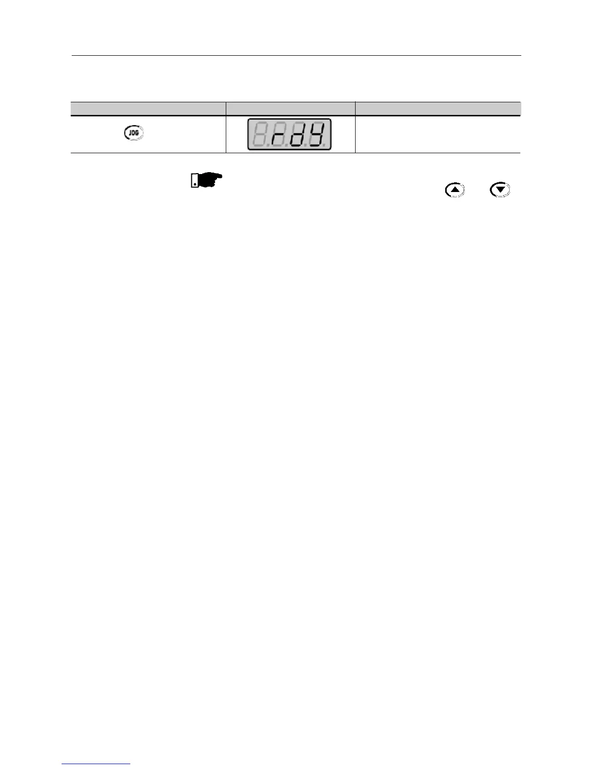
ACTION DISPLAY HMI DESCRIPTION
Release the key Motor decelerates down to 0 rpm

Table of Contents

Questions and Answers:

Question and Answer IconNeed help?

Do you have a question about the WEG CFW08 Vector inverter and is the answer not in the manual?

WEG CFW08 Vector inverter Specifications

General IconGeneral
Frequency Range0 to 300 Hz
Overload Capacity150% for 60 seconds
Protection DegreeIP20
CommunicationRS485, Modbus RTU
Voltage200 V to 240 V
Control ModeVector Control
Ambient Temperature-10°C to 50°C
Input Frequency50 Hz / 60 Hz
Output Voltage0 to input voltage
BrakingDynamic braking resistor (optional)
Protection FeaturesOvercurrent, overvoltage, undervoltage, overtemperature
Operating Temperature-10°C to 50°C
Cooling MethodForced air cooling (fan)
Humidity5% to 90% non-condensing

Related product manuals