Connections
4-4 | PLC300
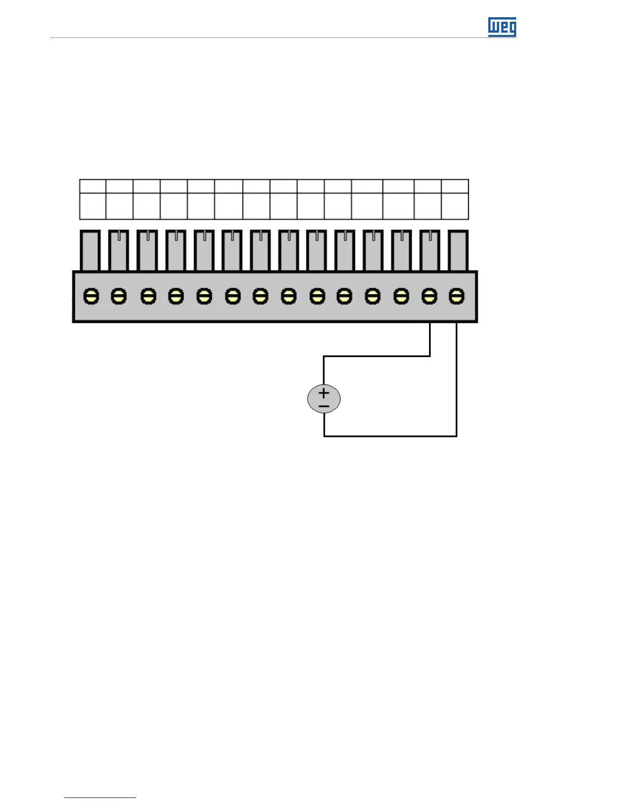
By means of the equipment setup, you can choose among the modes: voltage 0 to 10 V,
current 0 to 20 mA or current 4 to 20 mA.
When in current mode 4 to 20 mA, a broken wire alarm can be programmed. In this case,
if the input signal is below 2 mA, the alarm is generated, indicating the opening of the
current loop.
Below, a simple example of connection.
0 to 10 V
0 to 20 mA,
or
4 to 20 mA,
XC1
DI
1
1 74 102 85
11 12
13 143 96
DI
9
DI
5
DI
3
COM
1
COM
2
AI1
(+)
AI1
(-)
DI
7
DI
2
DI
10
DI
6
DI
4
DI
8
Figure 4.4: Example of connection of the analog input (XC1)
Note: AI1 operating mode must be chosen in the PLC setup: ‘Voltage 0 to 10 V’, ‘Current
0 to 20 mA’ or ‘Current 4 to 20 mA’.
4.6 ANALOG OUTPUT
The analog output AO1, 10 bit resolution, has output in current and/or voltage, with
independent terminals, which means there is no need to configure the operating mode;
simply connect the load to the correct terminal, in voltage or current.
In voltage, the output varies between 0 and 10 V. In current, the output range is from 0 to
20 mA, for a resistive load lower or equal to 500 Ω.
The voltage and current outputs can be used simultaneously, but obviously with the same
value, since they are the same output, just in different ways.