Connectors
3-2 | PLC300
3.1 CONNECTORS PINOUTS
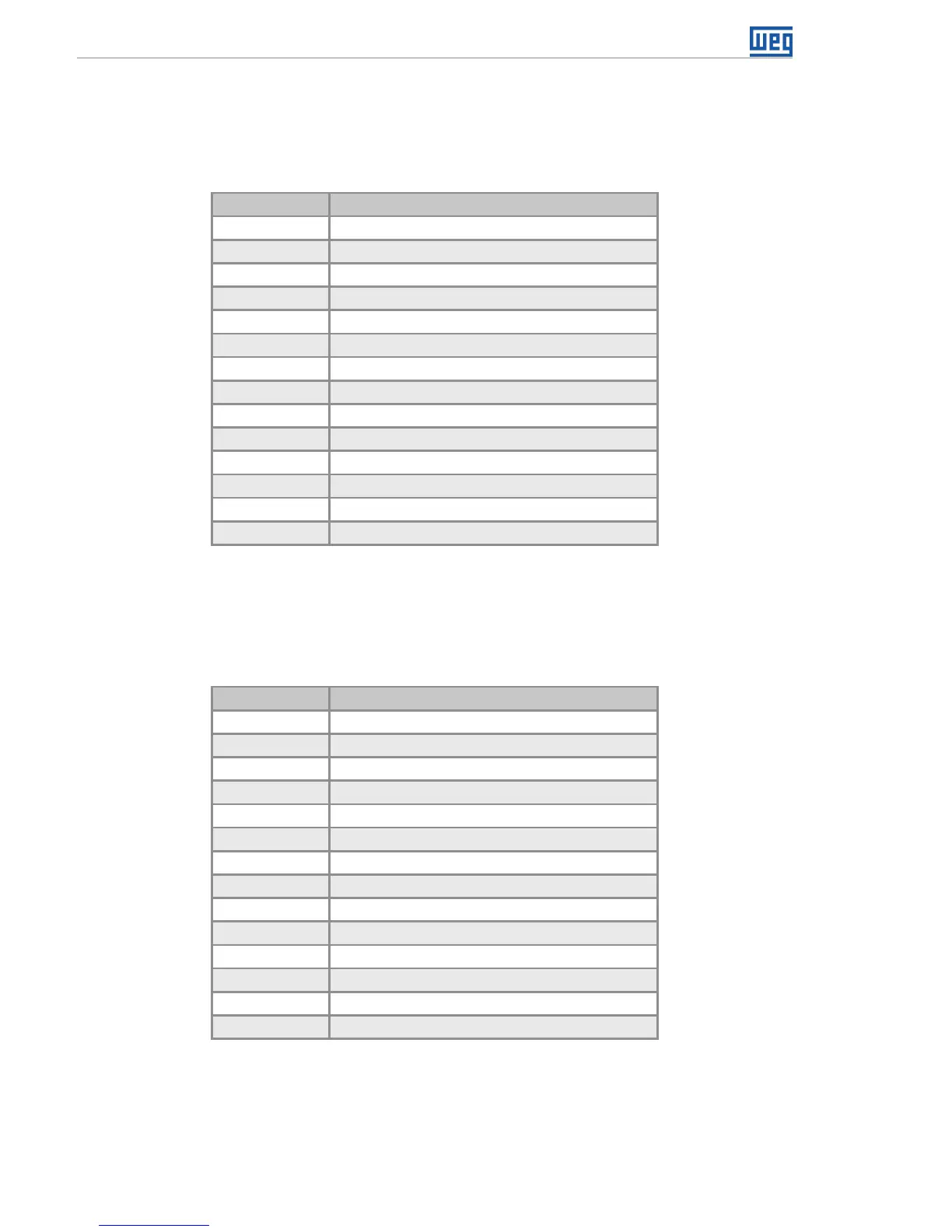
XC1 – Digital and Analog Inputs
Table 3.1: Function of the digital and analog input pins
Pin Function
1 DI1 - digital input 1.
2 DI2 - digital input 2.
3 DI3 - digital input 3.
4 DI4 - digital input 4.
5 DI5 - digital input 5.
6 DI6 - digital input 6.
7 DI7 - digital input 7.
8 DI8 - digital input 8.
9 DI9 - digital input 9 (fast)
(*)
.
10 DI10 - digital input 10 (fast)
(*)
.
11 Common of the inputs DI1...DI8.
12 Common of the inputs DI9...DI10.
13 (AI1+) analog input 1 (+).
14 (AI1-) analog input 1 (-).
(*) DI9 and DI10 can be used for reading encoder signals, A and B,
respectively.
XC2 – Digital, PWM and Analog Outputs
Table 3.2: Function of the digital, PMW and analog output pins
Pin Function
1 DO1 - digital output 1.
2 DO2 - digital output 2.
3 DO3 - digital output 3.
4 DO4 - digital output 4.
5 DO5 - digital output 5.
6 DO6 - digital output 6.
7 DO7 - digital output 7.
8 DO8 - digital output 8.
9 DO9 - fast output 9 (PWM).
10 GNDBB – 0 V digital outputs.
11 VBB – (20...30 Vdc) for the digital outputs.
12 AO1(V) – analog output 1 in voltage.
13 AO1(I) – analog output 1 in current.
14 AO1 – common.