Connections
4-8 | PLC300
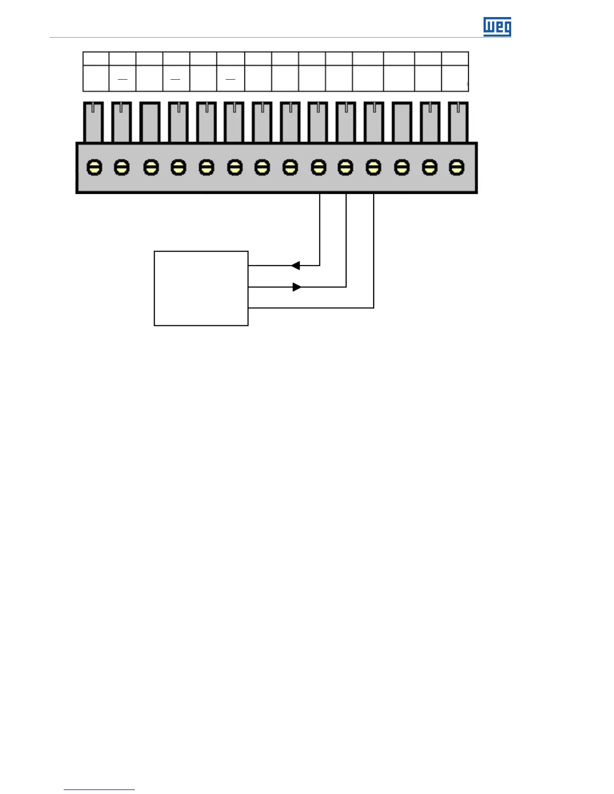
Modem
RS232
RX
TX
GND
XC3
ENC
A
ENC
A
ENC
B
ENC
B
ENC
Z
ENC
Z
ENC
+V*
ENC
0 V
232
TX
232
RX
232
GND
485
A
485
B
485
GND
1
7
4 102 85 11 12 13 14
3
9
6
Figure 4.8: Connecting the RS-232
Note: For further information, consult the manual for serial communication, available for
download on the website: www.weg.net.
4.9 RS-485 INTERFACE
Insulated, multipoint serial interface intended for network communication. It can operate
as master or slave with the Modbus RTU protocol.
The S1 key allows the connection of termination resistors.
The configuration of this interface is done by the setup menu.