Connections
4-6 | PLC300
(*)
5/12 V
A A B B Z Z 0 V
ENC
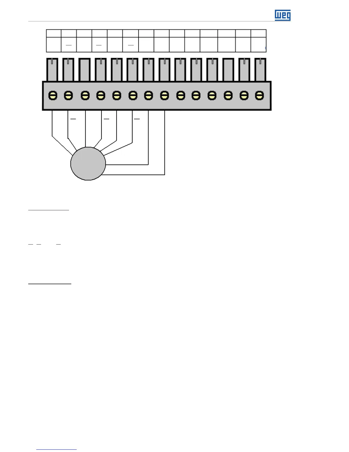
XC3
+V*
ENC
A
ENC
A
ENC
B
ENC
B
ENC
Z
ENC
Z
ENC
+V*
ENC
0 V
232
TX
232
RX
232
GND
485
A
485
B
485
GND
1 74 102 85 11 12 13 14
3
96
Figure 4.6: Encoder connection
24 V Encoder : You can connect a 24 V encoder, since externally powered and only signals
A, B, and Z are used.
The 0 V of the encoder must be connected to 0 V of XC3 (pin 8)
A, B and Z
signals are NOT tolerant to 24 V.
The signals A, B and Z can be used to fast counting and interrupts, also in 24 V.
Encoder PNP: if an encoder with PNP outputs is used, resistors of 1 K ohm must be
connected from the used signals to the 0 V.
E.g.: PNP encoder with A and B signals.