31
I N S TA L L E R S e c t i o n ( e n )
7113126.02 (3-08/13)
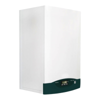
10.1 CONCENTRIC DUCTS
This type of duct is used to discharge exhaust fumes and
draw combustion air both outside the building and if a LAS
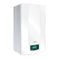
ue is tted. The 90° coaxial bend allows the boiler to be
connected to a ue-air duct in any direction as it can be
rotated by 360° It can also be used as a supplementary
curve combined with a coaxial duct or a 45° curve.
If fumes are discharged outside the building, the ue-air
duct must protrude at least 18 mm from the wall to allow an
aluminium weathering surround to be tted and sealed to
avoid water inltrations.
• A 90° bend reduces the total duct length by 1 metre.
• A 45° bend reduces the total duct length by 0.5 metres.
• The rst 90° bend is not included when calculating the maximum available length.
Secure the intake pipes with two galvanised screws with a diameter of 4.2 mm and a maximum length of 19 mm.
Before securing the screws, make sure that at least 45 mm of the pipe is inserted into the gasket (see the gures in "SECTION"
D at the end of this manual).
Make sure there is a minimum downward slope towards the outside of 1 cm per metre of duct length.
Measure the diaphragm with the gauge.
MODEL Length (m)
Using a DIAPHRAGM on
OUTLET DUCT (mm) “A”
1.24 F - 24 F
0 ÷ 1 Ø 43
1 ÷ 2 Ø 45
2 ÷ 5 No
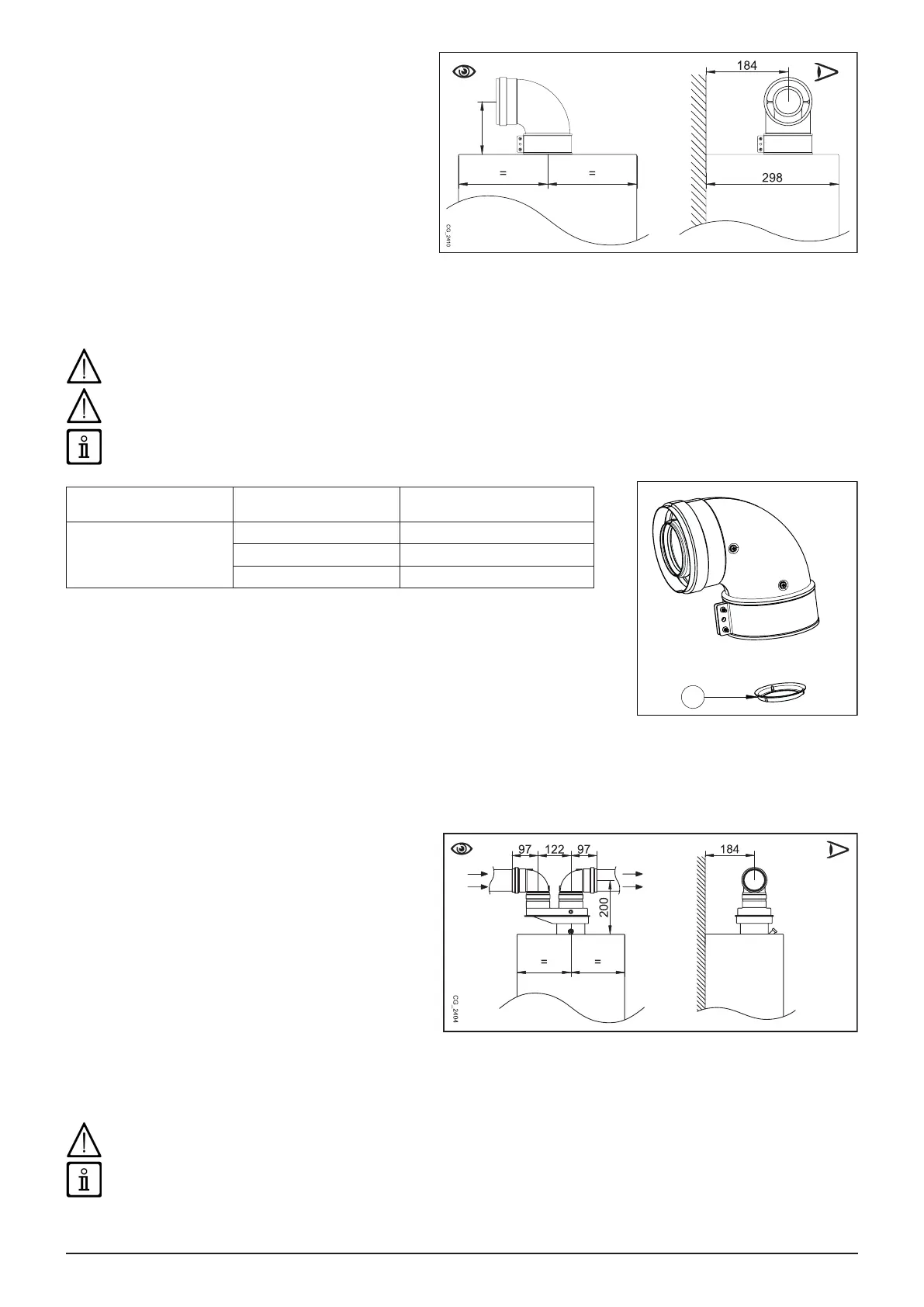
10.2 SEPARATE DUCTS
This type of installation makes it possible to discharge
exhaust fumes both outside the building and into single ue
ducts.
Comburent air can be drawn in at a different location from
that of the ue terminal.
The optional splitting accessory is xed to the boiler turret
(Ø 100/60 mm) and allows the air and fumes to enter/leave
the two separate ducts (Ø 80 mm). For further information,
read the assembly instructions supplied with the accessory.
The 90° bend is used to connect the boiler to the inlet and
outlet ducts, adapting them to various requirements. It can
also be used as a supplementary curve combined with a
duct or a 45° bend.
• A 90° bend reduces the total duct length by 0,5 metres.
• A 45° bend reduces the total duct length by 0,25 metres.
• The rst 90° bend is not included when calculating the maximum available length.
Make sure there is a minimum downward slope towards the outside of 1 cm per metre of duct length. In the event of installation
of the condensate collection kit, the angle of the drain duct must be directed towards the boiler.
Measure the diaphragm with the gauge.
116
A
CG_2117