GENERATOR
CONTROL
PANELS
DESCRIPTION
OF
SWITCHES
Thls
manually
controlled
,series
of WES1ERBEKE marine
diesel
generators
is
equipped with toggle switches
on
the
engine
control
panel
and,
optionally, at remote
panels.
All
three
switches are momentary contact type
and
serve
the
following
functions:
PREHEAT:
TI1e
PREHEAT
toggle switch serves two purposes:
preheating
the
engine
for
easy starting and defeating of
bypassing
the
engine
oil
pressure switch. The defeat function
turns
on
the
fuel
solenoid
..
instrument power
and
alternator
excitation.
When
the
PREHEAT
switch
is
depressed,
the
voltmeter,
·panel
lights,
gauges
and
meters
and
fuel solenoid
will
activate.
START:
The
START
toggle switch closes the
Kl
relay that
energizes
the
starter solenoid and activates the starter
..
While
the
PREHEAT
switch
is
still depressed, depressing
the
START
switch
engages·
the start solenoid. When.the engine
begins
to
fire,
the
START
switch should be released. The .
PREHEAt
switch
should
not
be released until
the
oil
pressure
reaches 5 -
10
psi.
STOPPING:
The STOP toggle switch is a nonnally closed
switch a
DC
path through the three automatic shutdown
switches to the
K2
run relay. Opening this switch termi-
nates this
DC
path to the
K2
run relay shutting
down
the
engine.
To
stop the engine, simply depress the STOPswitch. The
DC
path
to
the
K2
run relay is terminated, de-energizing
the
relay
and
the engine shuts
down.
The STOP switch
should be held depressed until
the
generator shuts
down
completely.
NOTE:
When
the
engine
is
shut
down,
the water temperature
gauge
and
the
oil
pressure
gauge will continue
to
register
the
last
temperature
and oil press
we
readings displayed.
They
will
retwn
to
zero
once
electrical power
is
restored.
EMERGENCY
STOP:
The EMERGENCY.
stop switch
on
the
side of
the
control
box.
is
normally closed.
When
depressed, it
will
open the
DC
circuit
to
the
control
panel and shut the engine down.
As
~he
switch is not toggled
it
can
be
used
when
petforming maintenance.
DESCRIPTION
OF
GAUGES
Coolant
Temperature
Engine coolant (water) temperature should normally
indicate
175°
to
195°
F
(80°
to
90°
C).
Engine
Oil
Pressure
Oil pressure (psi)
may
fluctuate depending
on
the
generator
load but should
range between between 30
to
60
psi.
DC
Voltmeter
Indicates the amount
the
battery is being charged should
show
13.5V
to
14.4V.
.
Hourmeter
Registers elapsed time and is used
as
a guide for
when
to
petform scheduled maintenance.
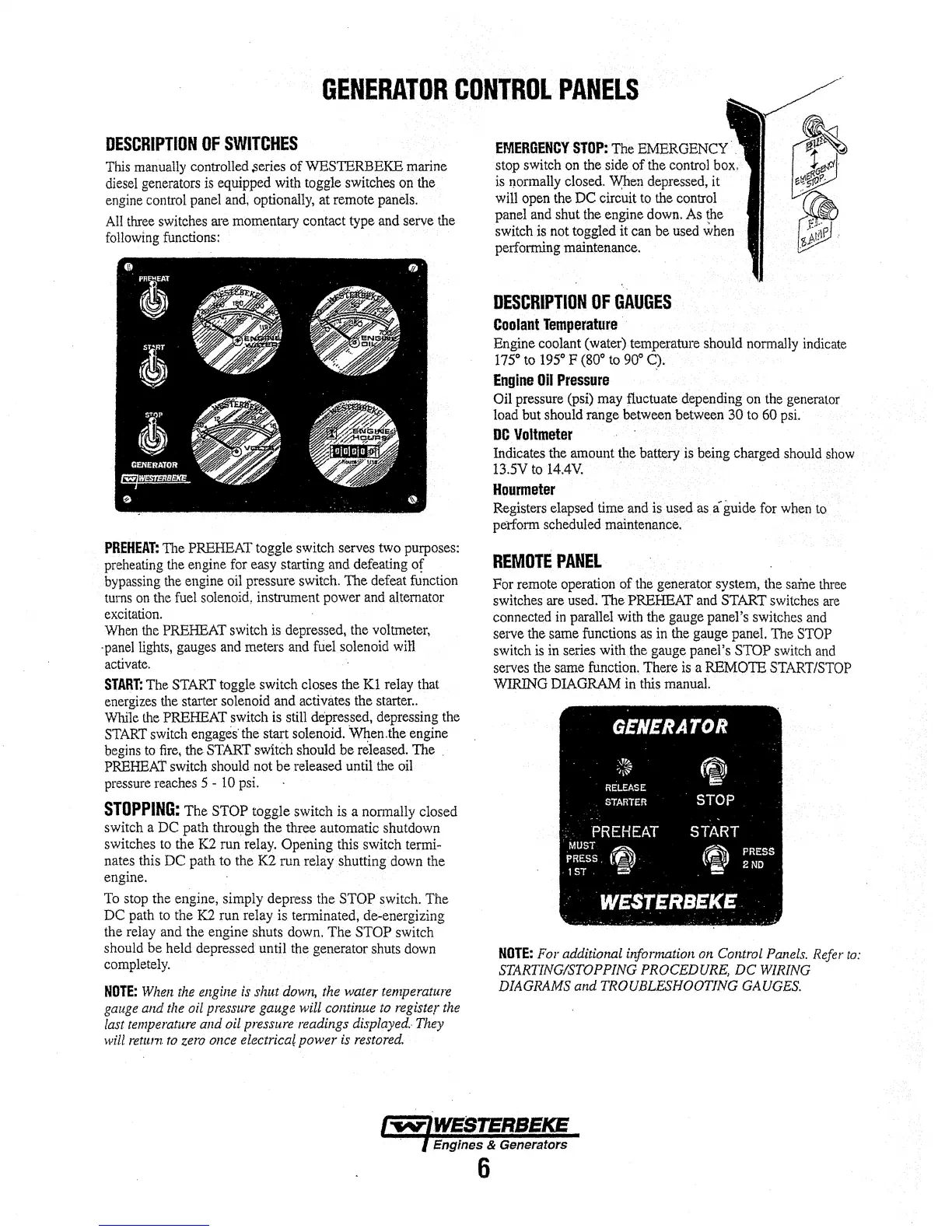
REMOTE
PANEL
For remote operation of
the
generator system,
the
same
three
switches are
used.
The PREHEAT
and
START
switches
are
connected
in
parallel
with
the gauge panel's switches
and
serve the same functions
as
in
the
gauge panel.
The
STOP
switch
is
in
series with
the
gauge panel's STOP switch
and
serves
the
same function. There
is
a REMOTE
START/STOP
WIRING
DIAGRAM
in
this
manual.
GENERATOR
:J%
~l~
RELEASE
STARTER
::
PREHEAT
•
MUST
-
PRESS.
tO
1ST.
e
ty
.
STOP
START
(
~').
PRESS
,f~~
2ND
·wESTERBEKE.
,
.....
,:
NOTE:
For
additional information
on
Control
Panels.
Refer
to:
STARTING/STOPPING PROCEDURE, DC
WIRING
DIAGRAMS and TROUBLESHOOTING
GAUGES.
£Engines
& Generators
6