ENGINE
ADJUSTMENTS
S.OKW
&
10.0KW
BTD
VALVE
CLEARANCE
ADJUSTMENT
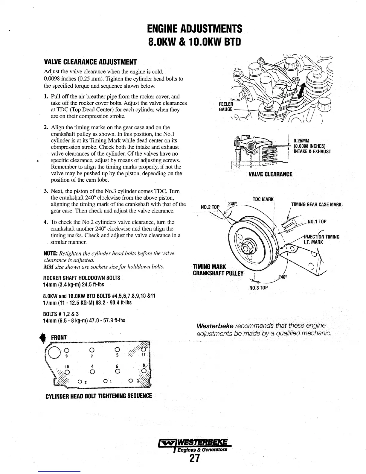
Adjust the valve clearance when the engine is cold.
0.0098 inches (0.25 mm). Tighten the cylinder head bolts to
the specified torque and sequence shown below.
1. Pull off the air breather pipe from the rocker cover, and
take off the rocker cover bolts. Adjust the valve clearances
at
TDC
(Top Dead Center) for each cylinder when they
are on their compression stroke.
2.
Align the timing marks on the gear case and on the
crankshaft pulley as shown. In this position, the No.1
cylinder is at its Timing Mark while dead center on its
compression stroke. Check both the intake and exhaust
valve clearances
of
the cylinder.
Of
the
val,ves
have no
~
specific clearance, adjust by means
of
adjusting screws.
Remember to align the timing marks properly,
if
not the
valve may be pushed up by the piston, depending on the
position
of
the cam lobe.
3. Next, the piston
of
the No.3 cylinder comes TDC. Turn
the crankshaft
240° clockwise from the above piston,
aligning the timing mark
of
the crankshaft with that
of
the
gear case. Then check and adjust the valve clearance.
4. To check the No.2 cylinders valve clearance, turn the
crankshaft another
240° clockwise and then align the
timing marks. Check and adjust the valve clearance in a
. similar manner.
NOTE:
Retighten the cylinder head bolts before the valve
clearance is adjusted.
MM
size shown are sockets size
for
holddown bolts.
ROCKER
SHAFT
HOlOOOWN
BOlTS
14mm
(3.4
kg-m)
24.5
ft-lbs
8.0KW
and
10.0KW
BTD
BOlTS
#4,5,6,7,8,9,10
&11
17mm
(11
-12.5
KG-M)
83.2-
90.4
ft-lbs
BOlTS#
1,2
& 3
N0.2
TOP
TIMING
MARK
CRANKSHAFT
PULLEY
I
0.25MM
~
(0.0098
INCHES)
,
INTAKE
&
EXHAUST
I
VALVE
CLEARANCE
~
N0.3
TOP
14mm
(6.5
· 8
kg-m)
47.0
·
57.9
ft-lbs
Westerbeke recommends that these engine
adjustments
be
made
by
a qualified mechanic.
0
7
4
li
0
0
O-z
Ot
CYLINDER
HEAD
BOLT
TIGHTENING
SEQUENCE
I"W"IWESIERSEKB
l EnglnN & Generators
27