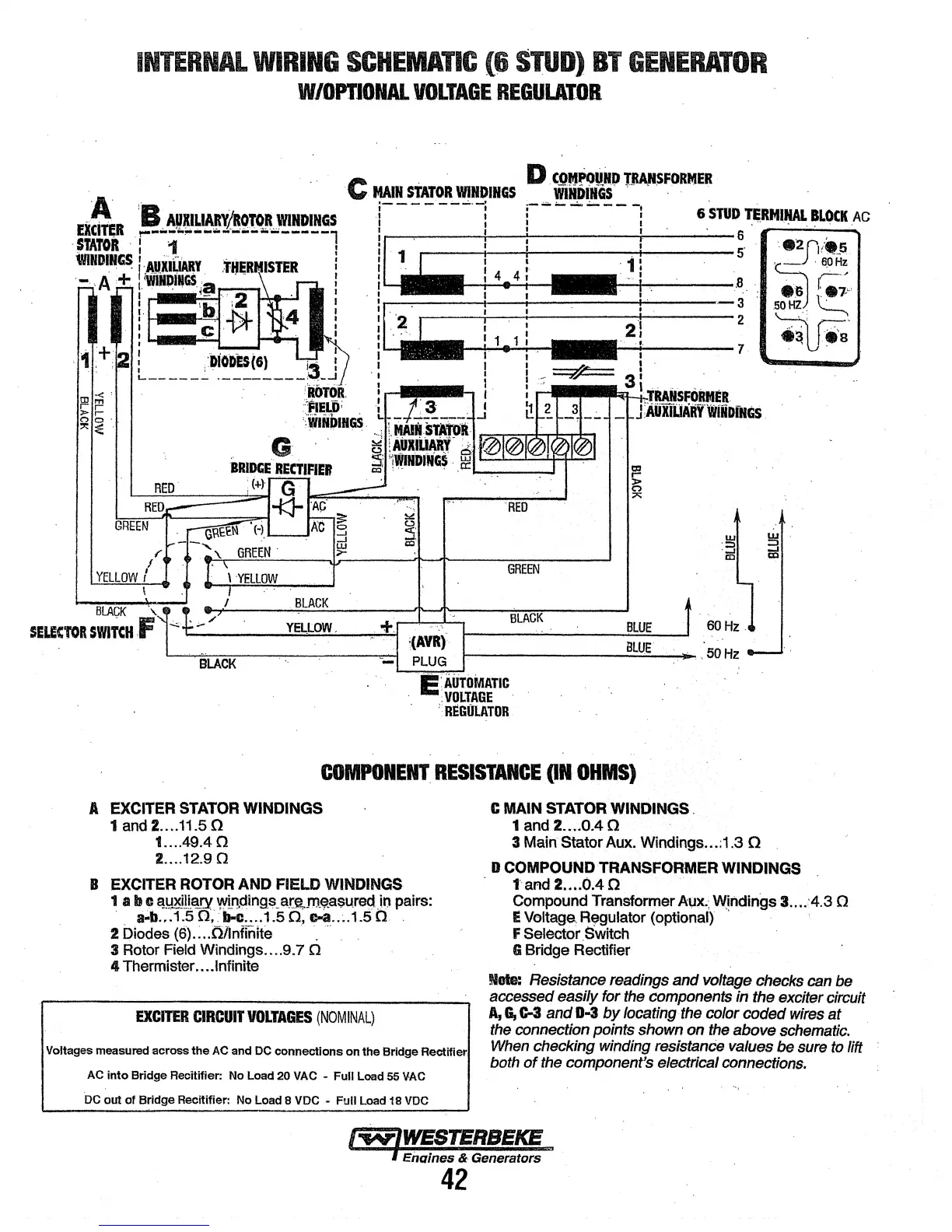
INTERNAL
WIRING
SCHEMADC
(6
STUD)
BT
GENERATOR
W/OPTJONAL
VOLTAGE
REGULATOR
("
I
YELLOW
I
I
\·YELlOW
I
RED
GREEN
BLACK
BLACK
\.
SELECTOR
SwtTcu
.f
BLAGK
~--------y~=-~OW--.
__
~+~-~~~~----~------~BL:~~~
~(AVR)
Bll/E
BLACK
PLUG
.50Hz
E;
iirriliviATIC
:VOLTAGE
·
'R~GOlATOR
COMPONENT.
RESISTANCE
(IN
OHMS)
A
EXCITER
STATOR
WINDINGS
1
and
2
•.•.
11.5
0
1 .... 49.4 0
2 ....
12.90
B
EXCITER
ROTOR
AND FIELD
WINDINGS
1 a b c
~~D.CJ!l.f!.ry
Wil1cting_s_
ar.ft,.m~$U.rec:tJn
pairs:
· ._b .. :1.5
o;:b-1:
....
1.5 n,
c-a
..
~.1.5
o .
2 blodes
(6).:
..
ollnfinite · .
···
3
Rotor
Field Windlngs .... 9.7 0
4 Thermister ... .Infinite
EXCITER
CIRCUIT
VOLTAGES
(NOMINAL)
Voltages measured across
the
AC
and DC
connections
on
the Bridge Rectifier
AC
into
Bridge Recitifier: No Load 20 VAC • Full Load 55
VAC
DC
out
of Bridge Recitifler: No Load 8 VDC - Full Load 18
VOC
C
MAIN
STATOR
WINDINGS.
1
and2
....
0.40
3 Main Stator Aux. Windings ... :1.3 0
D
COMPOUND
TRANSFORMER WINDINGS
1'
afld 2 .... 0.4 0 ·
Compound
Transformer
AI;JX.:
W:!ndings
3 ... .:4.3 0
E
Voltage.
Rl)lgulator
(optional) '
F Selector
.Switch
G Bridge Rectifier
Note:
Resistance readings and
voltage
checks
can
be
accessed easily for
the
components
in the exciter circuit
A,
a,
c-3 and
0·3
by
locating·
the
color coded
wires
at
the
connection points shown
on
the
above
schematic.
When
checking
winding
resistanee
values be
sure
to
lift
both
of
the
component's electrical
connections.
I~WESTERBEKE
~
Engines & Generators
42