TABLE
OF
CONTENTS
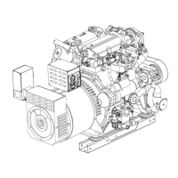
Parts
Identification
............................................
.2
Specifications
.......................................................
.
Introduction
.........................................................
3
8.0 Kw
BTD
................................................ 28
Diesel
Fuel,
Engine
Oil
and
Engine
Coolant.
......
5 10.0 Kw
BTD
.............................................. 30
Generator
Control
.Panels
....................................
6 11.0 Kw
BTD
.............................................. 32
Preparations
for
Initial
Start-Up
.........................
7 12.5 Kw BTD(A) ......................................... 34
Safety
Shutdown
Switches
and
Sensors
.............
8
BT
Generator
6
and
12
Stud
..............................
37
Starting/Stopping
Procedure
...............................
9
Voltage Regulator ........................................ 38
Generator
Break-In
Procedure
.........................
.1
o
BT
Troubleshooting Chart ........................... 38
Maintenance
Schedule
......................................
11
Internal
Wiring
Schematic
(12
Stud)
...............
.39
Cooling
System
..................................................
13
Resistance Values ........................................ 39
Raw Water
Pumps .......................................
14
Generator
Voltage
Adjustment
........................
.40
Intake Strainer .............................................
14
No
Load .......................................................
40
Heat Exchanger .......................................... .14
Full Load .....................................................
40
Thermostat ...................................................
15
Generator Frequency ..................................
.41
Zinc Anode .................................................. 16
6 Stud
AC
Connections ..............................
.41
Air
Intake
Silencer
............................................
16
Internal
Wiring
Schematic
(&Stud)
.................
.42
Fuel
System
.......................................................
17
Resistance Values ....................................... .42
Fuel Filters ...................................................
17
Internal
Wiring
Diagram
Fuel Lift Pump .............................................
18
3
Phase,
12
Wire,
Reconnectable
...................
.43
Engine
Lubricating
Oil
.......................................
19
AC
Voltage
Connections
BE
3
Phase
................
44
Oil Change ................................................... 19
Shore
Power
Transfer
Switch
...........................
.45
Oil Pressure ................................................. 19
w ..
o·
1nng
sagrams
...................................................
.
DC
Electrical
System
.........................................
20
#34651 - 8
BT
.............................................
46
Alternator .....................................................
20
#36412-
No Relays ..................................... 47
Starter
Motor
.....................................................
22
#36412-
Schematic No Relays ................... 48
Testing .................. , ...................................... 22
#36412
-Two
Relays .................................. .49
Disassembly ................................................. 23
#36412
- Schematic Two Relays ................. 50
Engine
Adjustments
...........................................
24
#41479-
BTD
and BTD(A) .......................
.51
Glow Plugs .................................................. 24
#41479
- Schematic .....................................
52
Injector ......................................................... 24
#43853-
BTD and BTDA ........................... 53
Throttle Control/Generator Frequency ........ 25
#43853
-Schematic
..................................... 54
Drive Belt Adjustment.. ............................... 25
#43944-
BTDA Diagram ............................ 55
Valve
Clearance
and
Timing
.............................
26
#43944
-
BTDA
Schematic ......................... 56
11.0 BTD and 12.5 BTD(A) ........................ 26
Remote
Oil
Fill
...................................................
57
8.0 and 10.0
BTD
........................................ 27
Power
Take
Off
System
.....................................
58
Lay-Up
and
Recommissioning
...........................
59
Suggested
Spare
Parts
......................................
61
Engines & Generators
1