INSTALLATION AND MAINTENANCE MANUAL
E1 FAMILY
LICENSED & SPREAD SPECTRUM RADIOS
JUNE 2001
SECTION 2: PRODUCT DESCRIPTION PAGE 3-75
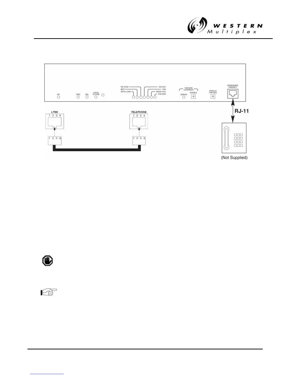
FigureFigure 3 3-- 19: RJ19: RJ-- 11 Orderwire Telephone Connection11 Orderwire Telephone Connection
2. Using a standard RJ-11 telephone cable, connect a standard electronic telephone (a touch
tone phone, complete with dialer; a handset by itself will not work) to the Orderwire
connector on the Lynx front panel. This connector is wired identically to a standard two-wire
telephone jack, see Figure 3-19 for details.
3. With a telephone connected to each Lynx terminal on opposite ends of the link, either
telephone can be used to “dial-up” the far-end location. Simply pick up the handset of the
near-end telephone and dial the two-digit address of the far-end Lynx terminal. The far-end
terminal’s internal ringer and the connected telephone will ring, and if answered, two-way
full-duplex voice communication is established.
If using the Orderwire or Network management functions, all Lynx
radios connected must have unique address settings (telephone
numbers).
The orderwire address is set by two rotary switches on the rear
panel of the Lynx radio. Use as small screwdriver to select the
orderwire address (01 through 99).