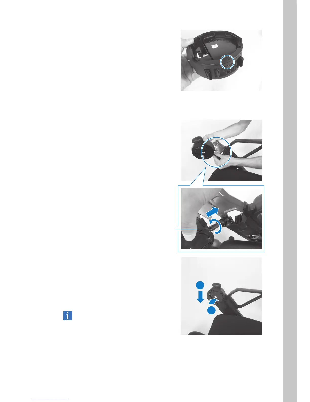
7. Install the ring-shaped cover that was
removed in the previous step onto the inside
of the control assemblies (opposite side).
Align the box “ | ” with the cover “
p
” and
rotate clockwise to fasten in place.
8. Repeat Steps 2 - 7 and move the ring-
shaped cover on the opposite-side box in
the same way.
9. Switch the location of control assemblies.
Insert the connector and rotate the base lock
clockwise to lock it.
Rotate the lock until a click sound is heard.
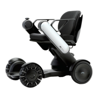
10. Install the control assemblies onto the arms.
1) Slide the control assemblies onto the
arm.
2) Slide control assemblies downward.
When a click sound is heard and the
white lever rises, the box is fastened in
place.
Move control assemblies up, down, left, and
right, and check that it is locked in place.
Lock
2
1