5.6.3 Auxiliary blower
The auxiliary blowers supply air from the engine room through the duct into the scavenge air
receiver during the engine start and operation at low load. The flaps prevent the back flow of air
to the scavenge air receiver during usual operation of the turbochargers and during engine stop.
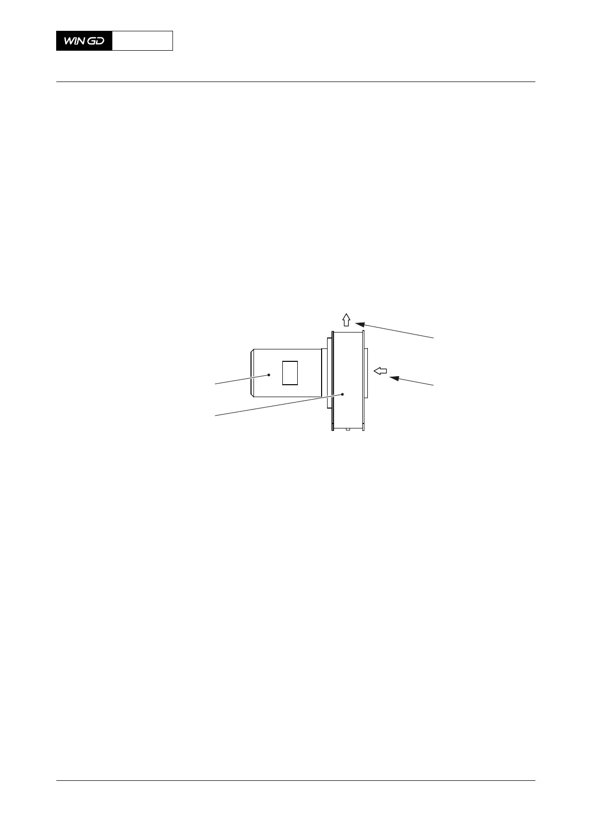
The electric motor (004, Figure 5-35) operates the auxiliary blower (003).
The pressure relief valve is installed to protect the scavenge air receiver, when pressure is more
than set limit.
The auxiliary blowers are installed on the scavenge air receiver, refer to section 5.6.1 Scavenge
air receiver.
Fig 5-35 Auxiliary blower
Legend
001 Air outlet 003 Auxiliary Blower
002 Air inlet 004 Electric motor
During the engine start operation, the auxiliary blowers start one by one at two or three seconds
interval, to avoid electric overload.
Minimum one auxiliary blower is necessary to start the engine.
NOTE: During emergency operation, the auxiliary blowers can be manually controlled when all
the scavenge air pressure transmitters are faulty.
During the engine operation, when the turbochargers supply sufficient air pressure in the scavenge
air receiver, the auxiliary blowers stop automatically by tunings depended setup and starts again
if required, (Delta bar).
The auxiliary blower switch box (refer to section 5.6.4 Auxiliary blower switch box) is the interface
between the operator and auxiliary blower and gives data about the condition of the auxiliary
blowers.
X92-B
AA00-6545-00AAA-043A-A
Operation Manual Auxiliary blower
Winterthur Gas & Diesel Ltd.
- 180 - Issue 002 2021-11