4.12.3 LP SCR control system
The main tasks of the WinGD control system for the LP SCR system are as follows:
•
Calculate the setpoint position for the turbine bypass valve (V4) to control the exhaust gas
temperature.
•
Control the operation of the auxiliary blowers.
•
Calculate the setpoint for the urea dosing unit.
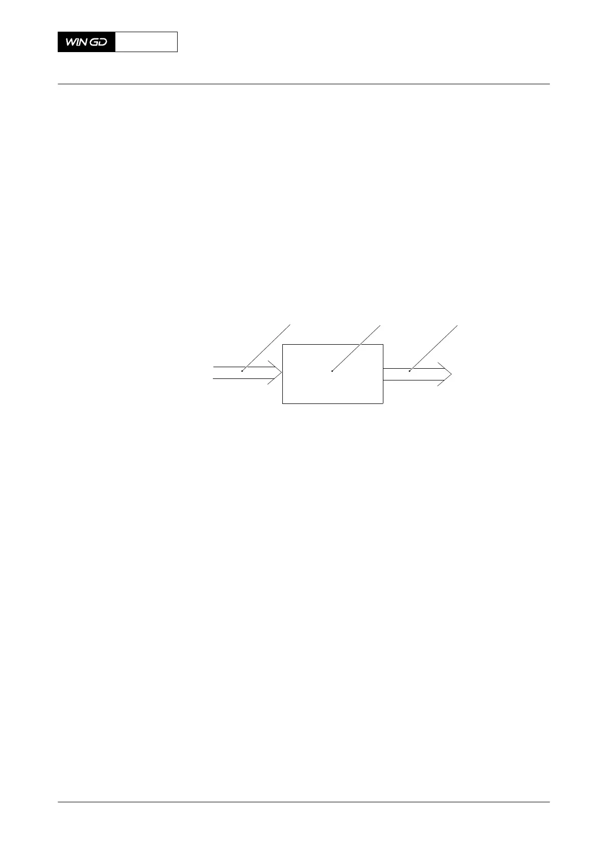
Related to the input signals the LP SCR control system gives the related signals to the LP SCR
system, refer to Figure 4-15.
Fig 4-15 LP SCR control system layout
Legend
001 Input signals 003 Output signals
002 LP SCR control system
The main input signals are as follows:
•
Engine parameters
•
Prepare Tier III command from RCS
•
Tier III command from RCS
•
Position of turbine bypass valve (V4)
•
Different temperatures and pressures
The main output signals are as follows:
•
Different temperatures and pressures
•
Signals to enable or disable the LP SCR system
The principal control configuration of the LP SCR system is shown in Figure 4-16.
X92-B
AA00-9270-00AAA-043B-A
Operation Manual LP Selective catalytic reduction system
Winterthur Gas & Diesel Ltd.
- 96 - Issue 002 2021-11