OLED DISPLAY
MFL Info screen
Switch on the MFL and by pushing the rotary knob (at the right of the display) all the basic information are
displayed:
Product name
Serial number
Class and Hardware version
Firmware version
Application Firmware version
Turning the rotatory knob the list of the modules is displayed:
Turning the rotatory know again the list of the options installed is displayed:
Push the rotary knob to enter the Main screen
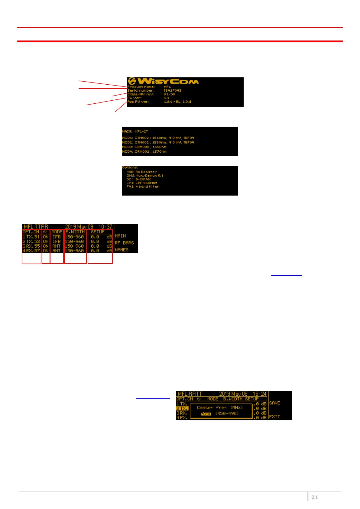
Main screen
0
In the left top side of the main screen there is the “NAME” of the MFL that is settable in the Main menu. At the right
of "NAME", date and time are displayed.
❶ The first number (1 to 4) identify the link (same reference on back-side connectors).
TX or Rx if that link has a laser transmitter or a receiver, respectively.
The last number after the dot, 51/53/55/57 refers to the CWDM link frequency: 1510/1530/1550/1570nm.
❶ ON/OFF status of specific link
❶ There are 3 possible modes:
o ANT as remote antenna link
o IFB as remote intercom link optimized on a 0dBm reference input
o <n>ifb as remote intercom link optimized for <n>carriers
❶ on TX opt. modules (i.e. 1 TX.51) ANT configuration there are several bandwidth configuration according to
the filter installed in the MFL (see filter option)
❶ Pushing on lower right button the last column shows:
o CUR/PWR show the RF/optical power in reception or the laser current in TX module
o RF LEV shows the value of the RF power level
o “GAIN” that is the relative gain of the link. Here it is possible to change the gain in the operating range.
NOTE: unless you have special needs we recommend to keep GAIN to 0 dB and enable the optical power
correction on the receiver side, since this is already optimized for most applications!