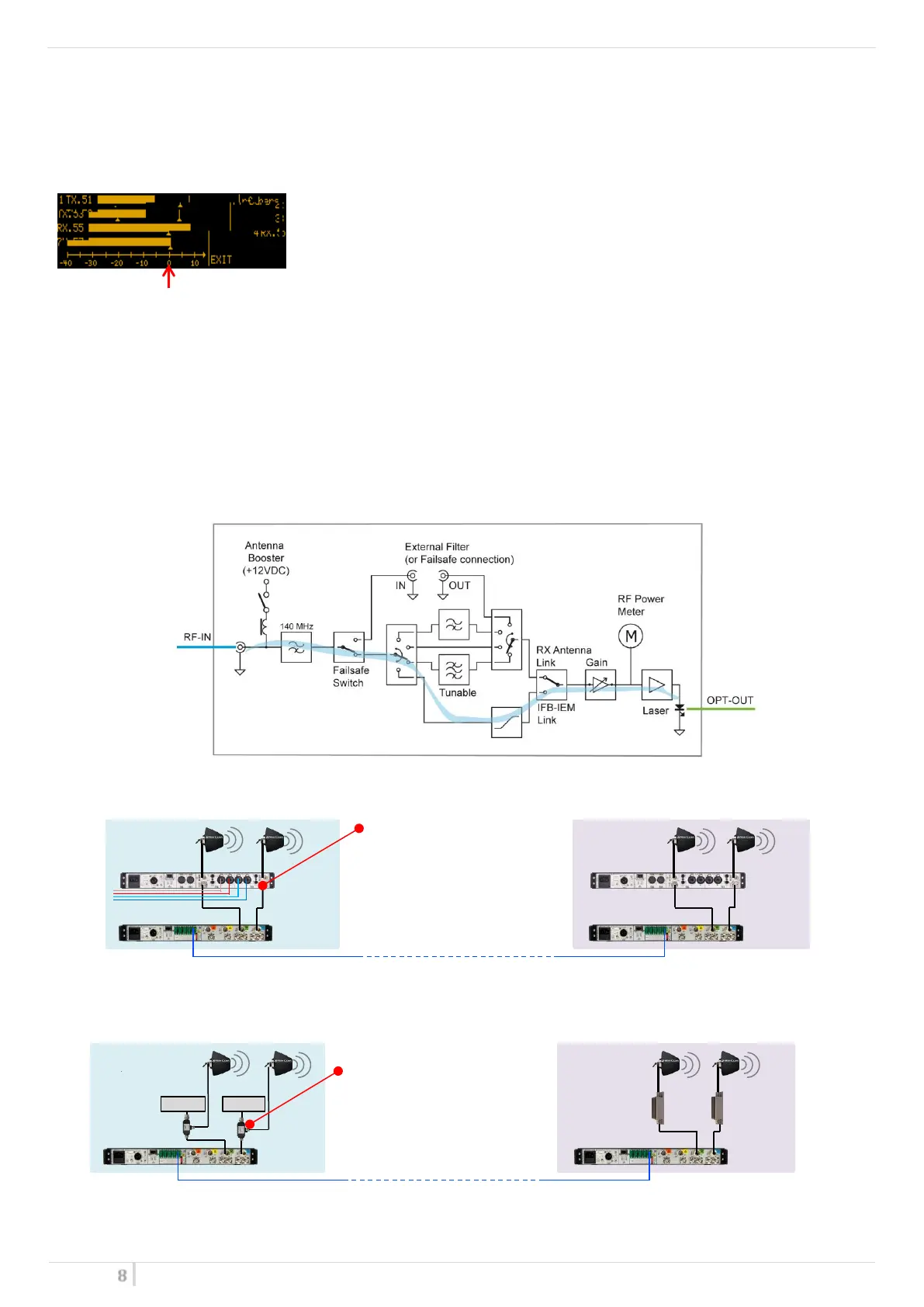
Optical Transmitter Module
Optical TX module is designed to modulate RF signal to optical fiber.
The module is equipped with a RF Power Meter which measures in real time the RF power input.
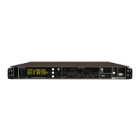
A dedicate RF BAR menu gives indication of average RF level for each modules.
“0” is the reference level
For TRANSMISSION SYSTEM (MODE: IFB), “0” level means 0dBm
For RECEPTION SYSTEM (MODE: ANT), “0” level means -20dBm (≈87 dBµV)
WARNING:
RF LEVELS HAVE TO REMAIN < “10” in order to avoid intermodulation issue.
NOTE: RF level depends on the band setting (filter).
RF bar are diseabled in TRANSMISSION MODE: <n>ifb
TRANSMISSION SYSTEM (MODE: IFB)
When the module is configured for TRANSMISSION SYSTEM (MODE: IFB), input RF power has to remain with in the
range 0.25mW ÷ 4mW (-6dBm÷6dBm).
Wisycom MTK952 trasnmitter with MS option provides a dedicated port at 0dBm of reference to connect directly
into the MFL TX module.
With different transmitters than MTK952, the user has to make sure that input RF power is within the range, by
adding RF attenuators if input RF power is too high.
-6 dBm ÷ 6 dBm
0dB is the reference level
Master conf.
up to several tens of kilometers
(depending on the fiber)
up to several tens of kilometers
(depending on the fiber)