J
Julie FriedmanAug 14, 2025
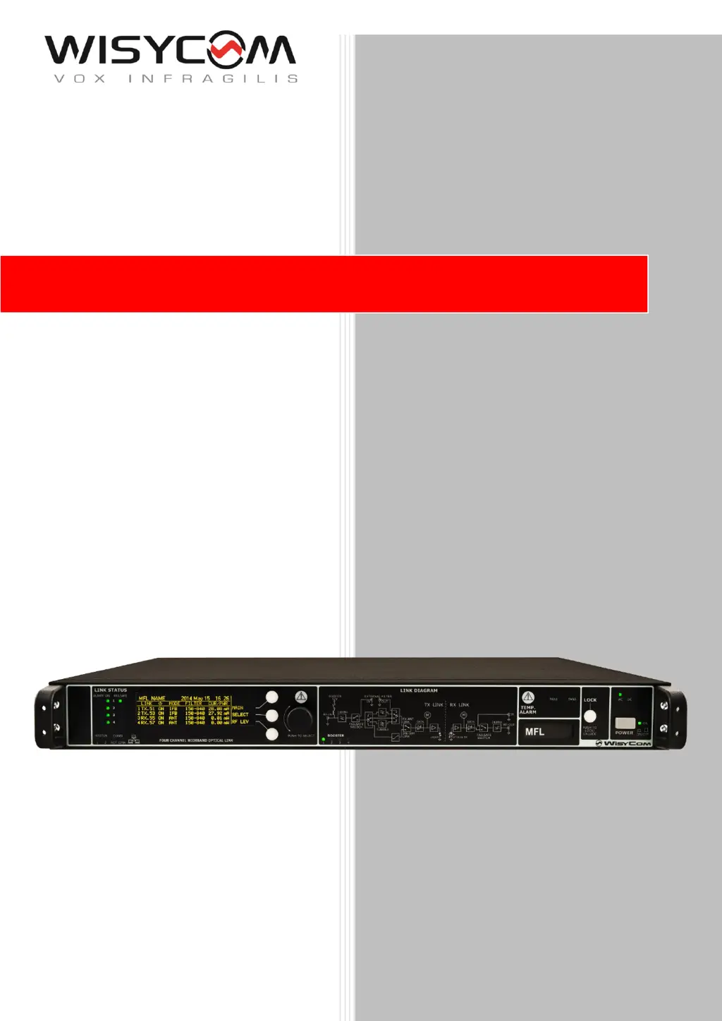
How to troubleshoot high temperature on WisyCom Switch?
- JJill MartinezAug 14, 2025
To troubleshoot high temperature issues on your WisyCom Switch, you can try the following: 1. Check if the two fans are working properly. Refer to alarm codes 0x02 or 0x03 on the alarm list. 2. Switch off the MFL (presumably a module or function) to allow for cooling, and then check the ambient temperature of the location. 3. Clean the ventilation grids to ensure proper airflow.