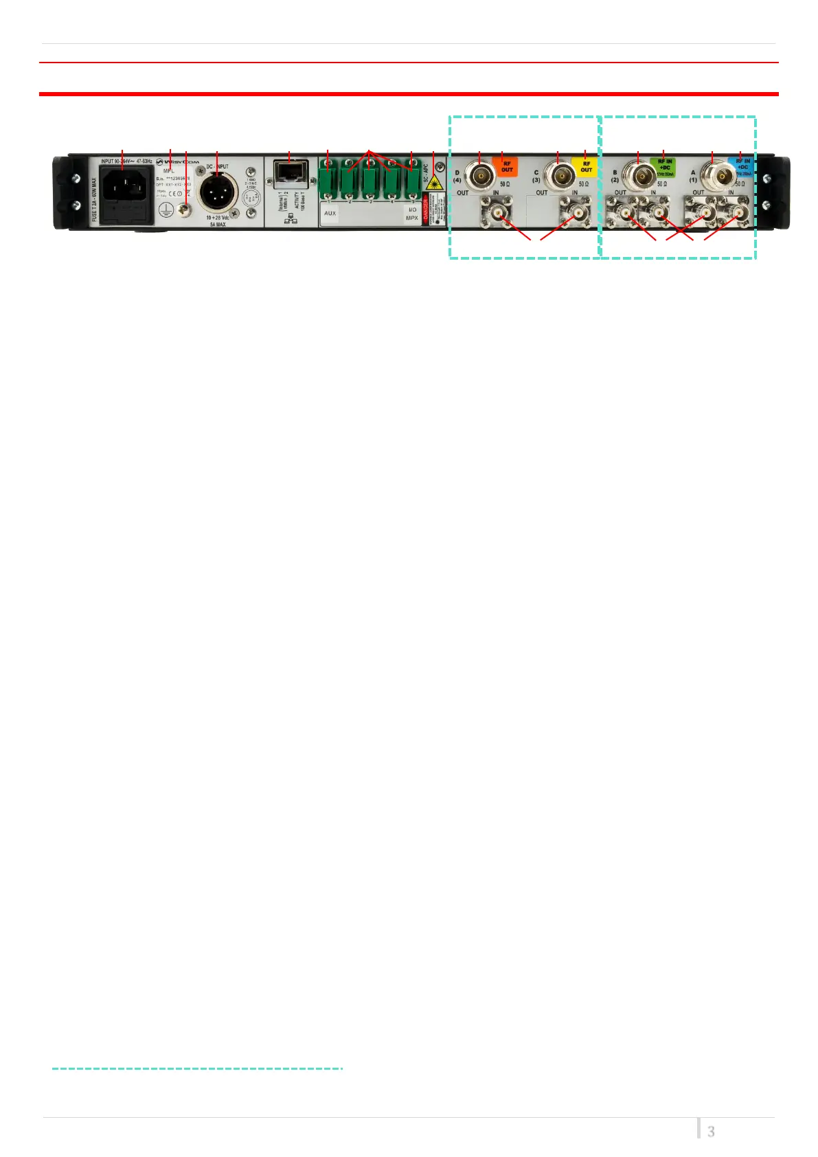
REAR PANEL
❶ ❷❸ ❹ ❺ ❻ ❼ ❽ ❾ ❿⓫ ⓬ ⓭ ⓮ ⓯ ⓰ ⓱
⓲ ⓳ ⓴
❶ AC Power Plug AC mains power input, IEC Connector 90-264 Vac
❷ Product label with Serial Number and Options installed
❸ Ground point To connect the MFL rack frame to ground
❹ DC Power Plug (only with MFL-DC option) DC power input, 10-28Vdc, Max 5A
❺ Ethernet socket (RJ45) for connection to a network or computer
❻ Auxiliary optical Input/Output Connector
❼ Optical Input/Output Connectors where the optical signals are divided by wavelength
❽ Optical Input/Output Connector where the optical signals are multiplexed (only with MFL-OMX
option)
❾ Optical safety label
❿ Output N connector female 50Ω (*)
⓫ Orange label: relative laser wavelength = 1570 nm
⓬ Output N connector female 50Ω (*)
⓭ Yellow label: relative laser wavelength = 1550 nm
⓮ Input N connector female 50Ω with switchable 12V boosting power (only on transmitter modules) (*)
⓯ Green label: relative laser wavelength = 1530 nm
⓰ Input N connector female 50Ω with switchable 12V boosting power (only on transmitter modules) (*)
⓱ Blue label: relative laser wavelength = 1510 nm
⓲ BNC-F connector 50Ω for failsafe option (on receivers modules) (*)
⓳ BNC-F connector 50Ω to connect the output of an external filter (on transmitters modules) (*)
⓴ BNC-F connector 50Ω to connect the input of an external filter or for failsafe option (on transmitters
modules) (*)
* In this example. Other configurations on request.