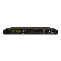
FRONT PANEL CONTROL AND FUNCTIONS
MFL allows an easy and quick configuration using buttons, push knobs and display.
The front panel is functionally divided in the following section:
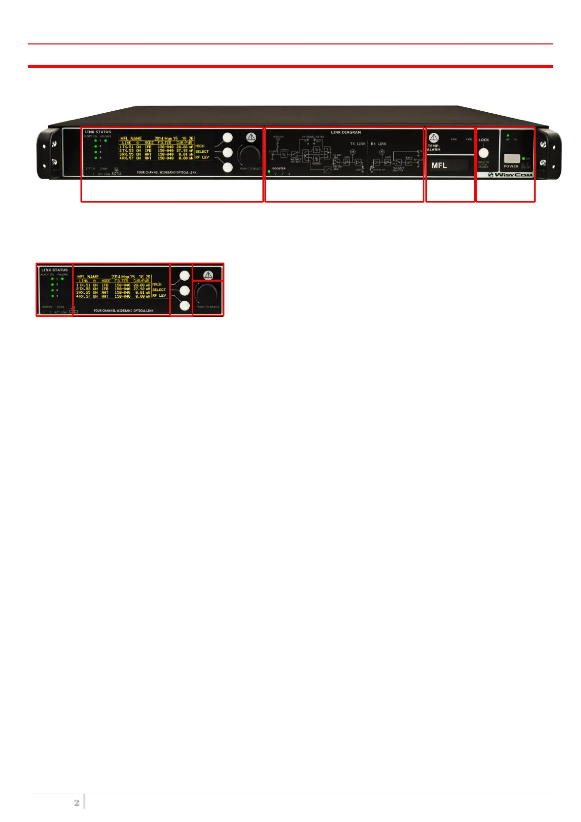
A – LINK STATUS
Transmitter / Receiver configurations
❶ Connection status:
The first column of LEDs indicate Alarms
The ON column indicate if a module is ON
The FAILSAFE column indicate if the Failsafe option is enabled
STATUS and CONN, showing the LED indications of the Ethernet module on the rear panel
❷ Display (64 x 256 pixels yellow OLED display)
❸ 3 push buttons (membrane). The function of each button (upper, middle and lower) will be readable
from the contextual menu on the display.
❹ Warning (YELLOW) and Alarm (RED) light indicator
❺ Push rotary knob. Rotate and push to select.
B – LINK DIAGRAM
This part shows the block diagram of one complete channel and the BOOSTER supply if enabled from the
transmitters
C – TEMPERATURE ALARMS & CONFIGURATION LABEL
TEMP. ALARM: indicate eventually high temperature on the device.
FAN1/FAN2: these LEDs turn on if faults occur to the cooling system.
CONFIGURATION LABEL: name and configuration of the device.
D - LOCK & POWER
LOCK: it locks the editing of the display.
POWER: ON/OFF square powering button turns on/off the MFL. Above the power button, there are two
LEDs to indicate the type of power supply.
NOTE: If both AC/DC power are supplied, both LEDs turn on but the device uses only AC power supply