22
3062547_201802
16 Oilconnectioninthesingleline
system
Secure the lter vent combination with the integrated shut-off valve and retainer to the
positions provided for this. In doing this, the oil hose should be a max. of 90 cm outside
of the housing during rear wall implementation. The lter vent combinations must be
freely accessible once installed.
Onlyuselterinsertsmadeofsinteredplasticwith25-40μmto
preventcontaminationoftheoilnozzlewithintheserviceinterval.
Contaminatedoilnozzlesleadtotheboilerfailing.
The system must be connected as a single line system. A lter/air vent valve combination
with an integrated shut-off valve from the Wolf product range must be installed.
Oldertwo-linesystemsmustbeconvertedtosinglelinesystems.Two-
linesystemsleadtoacceleratedoilageingandthepenetrationofair
intotheoil.Theyarenolongerinlinewiththelatesttechnology.
Onlymaterialsthataresuitableforoillinesshouldbeused.Inthecase
ofcopperpipes,onlymetalliccompressionttingoliveswithsupport
sleevesarepermissible.Theyareareliablemeansofpreventingairintake.
In accordance with TRÖl, the oil supply shall be checked for its perfect
condition and proper installation and a nal tightness check shall be carried out.
This inspection shall be performed:
• Before commissioning
• For underground oil lines, before they are covered and
• after work on the oil lines (except for oil lter changes)
Inordertopreventdamagetotheoilpump,thefueloilmustbesupplied
tothelterusingasuitablemanualpump.
Thetemperaturemustnotfallbelow+5°C.Externaltanksmusthave
supplementaryheatingfacilities.Theoillinesmustbeinstalledwhile
thesystemisisolatedfromtheelectricalsupplyinordertoavoidleaks.
Contaminantscanleadtosystemdamage.Theoillinemustbeushed
priortocommissioning.
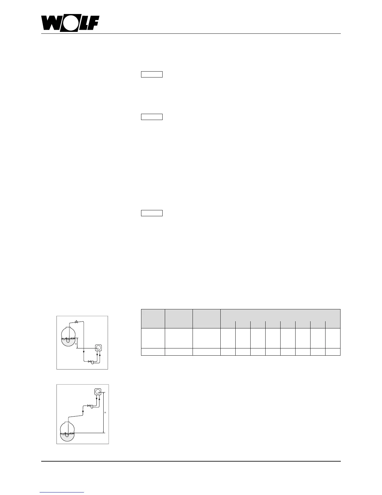
The maximum possible suction line length results from the pressure losses on the
pipes and ttings and the inlet height. All vertical and horizontal pipes are identied as
line lengths.
The following table can be used for sizing. When sizing the line lengths, the lter, non-
return valve and six 90° bend resistances are already taken into account.
Installing suction lines of a max. of 40 m is recommended.
The maximum permitted negative pressure in the suction line is 0.3 bar.
Device
Throughput
Inner line
Ø
Inlet height H (m)
kg/h mm +4 +3 +2 +1 0 -1 -2 -3
COB-15
COB-20
COB-29
Up to 2.5 4 40 40 40 40 40 35 25 13
COB-40 Up to 3.7 4 40 40 40 38 29 22 15 9
Floating or raised suction shall be used, if permitted.
Floating suction is not permitted for underground oil tanks or for oil tanks for which a
special draw-off device is prescribed by the manufacturer.
Oil lines that are too large may lead to operating faults caused by trapped air. The oil
supply must therefore be designed with an interior line diameter of 4 mm.
Oillter/oillineinstallation
Note
Note
Note
Maximumlinelengthsinsingleline
systems
Floating air
extraction
Oil pump,
burner
+
Anti-trap valve
Fig.:
Single line system with pump lower than tank
Fig.:
Single line system with pump higher than tank
Oil pump,
burner
Floating air
extraction
-