25
3062547_201802
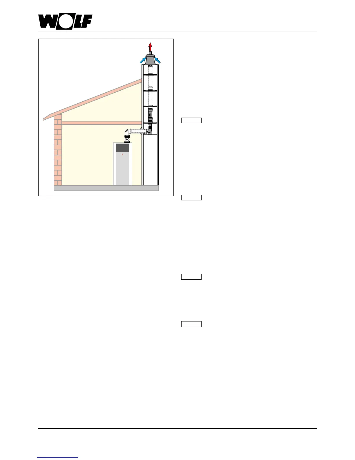
18 Installationoftheair/uegas
routing
Fig.: Example of a C93x balanced ue system
UseonlyoriginalWolfcomponentsforuesandconcentric
balanceduesystems.
Observethetechnicalinformationregardingventilationair
supply/uesystemspriortoinstallingtheueormaking
theueconnection(seetheTechnicalInformationchapter)!
As regulations in the individual Federal States [Germany] differ,
we recommend consulting the relevant authorities and local ue
gas inspector prior to installation.
Between the ue terminal and the roof surface, there must be a
clearance of at least 0.4 m.
Flue connections are created using female connections and
gaskets. Always arrange female connections against the
direction of the condensate ow.
The balanced flue should be installed with a
slopeofatleast3°(6cm/m)totheoilcondensing
boiler.Fitspacerclipstosecuretheequipmentin
position.
Intheworstcasescenario,alesserslopeofthe
air/uegasroutingsystemmayleadtocorrosion
oroperatingfaults.
Alwaysbevelordeburrtrimmeduestoensure
gas-tight installation of pipe joints. Ensure
that gaskets are tted correctly. Remove all
contamination prior to installation - never t
damagedparts.
Note
Note
The local ue gas inspector must have clear
accesstotheuegastestnipples.
Note
ForCOB-15/-20/-29,thesuppliedfluegastest
nipplesmustbefittedtotheair/flueoutlets.
Alternatively, the flue gas test nipples may
also be directly fitted horizontally after the
87° bend fitted to the boiler. When doing
this,ensurethatthebalancedflueisrouted
over the appliance in such a way that
the displacement device can be removed
(minimumclearanceviaCOB-15/-20/-29is30
cm;forCOB-40itis40cm).
Note