46
3062547_201802
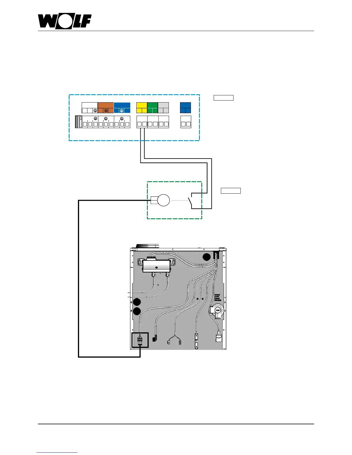
28 Cascadeoperation-Fluegasdamper
installation/wiringdiagram
M
230V~
Netz
KKP
LP
N
N
N
L1
L1
L1
L1
L1
L1
N
N
N
AF SF
E1
eBUS
+
-
1 1
2 2
a
b
12 12 12
12
COB terminal box
Flue gas damper
with servomotor
Limit switch
COB-15/20/29/40
Programmable output A1
(230VAC; 200VA)
Note
Fluegasdamperlimitswitch
mustbepotential-free.
Otherwise,theCOBcontrol
unitisbedestroyed.
Note
Thecontractorparameter
HG13(E1input)mustbesetto5
and
HG14(A1output)mustbesetto7!
Otherwise,theboilersdonotchangeinto
heating mode.
Power supply (230 VAC; 200 VA)
Fluegasdamperwiringdiagram
Junction box
on site