59
3062547_201802
Air/uegasrouting
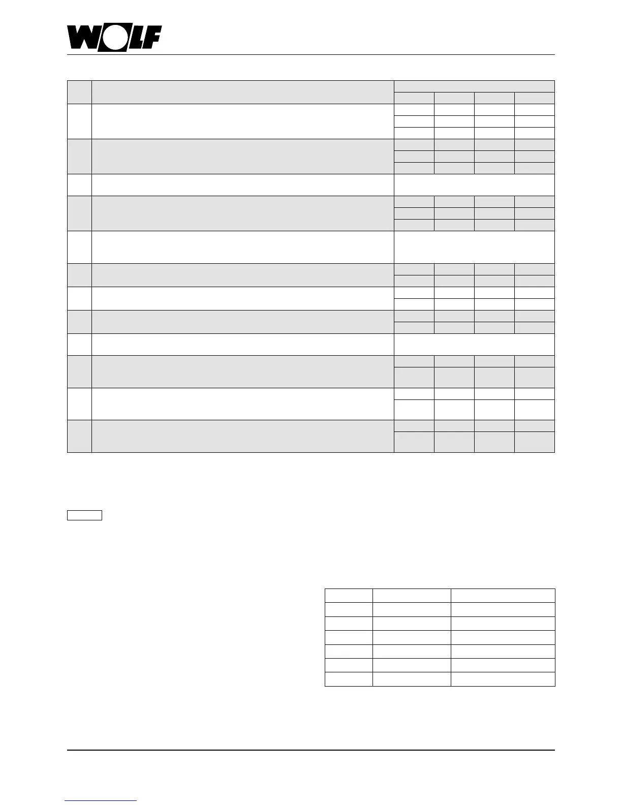
36 Technicalinformation
Condensingboilerversions
Maximumlength
1)
COB-15 COB-20 COB-29 COB-40
B23
Flue in a duct and combustion air directly via the appliance
(open ue)
DN 60
20 - - -
DN 80
30 30 30 -
DN 110
- - - 30
B33 Flue in duct with horizontal, concentric supply line (open ue)
DN 60
18 - - -
DN 80
30 30 30 -
DN 110
- - 30
B 33
Connection to a moisture-resistant chimney with
horizontal concentric connection pipe (open ue)
Calculation to EN 13384
(balanced ue manufacturer)
C33x
Vertical concentric roof outlet through a pitched or at roof,
vertical concentric balanced ue for installation in a duct,
(balanced ue)
DN60/110
9 - - -
DN 80/125
24 22 18 -
DN110/160
- - - 14
C43x
Connection to a moisture-resistant balanced ue chimney,
maximum pipe length from centre of boiler bend to connection
3 m (room sealed)
Calculation to EN 13384
(balanced ue manufacturer)
C53
Connection to the ue in a shaft and supply air pipe through an
external wall (balanced ue, supply air pipe 4 m, 1x bend 87°)
DN 80/125
30 30 30 -
DN110/160
- - - 30
C53x
Connection to a ue on an external wall
(room sealed/balanced ue)
DN 80/125
30 30 30 -
DN110/160
- - - 30
C53x
Connection to the ue in a shaft and supply air through an
external wall (balanced ue, supply air pipe 4 m, 1x bend 87°)
DN 80/125
30 30 30 -
DN110/160
- - - 30
C83x
Concentric connection to moisture-resistant ue gas chimney and
combustion air through external wall (room sealed)
Calculation to EN 13384
(balanced ue manufacturer)
C93x
Vertical ue for installation in a shaft, with minimum dimensions
rigid or exible with horizontal concentric connection pipe
DN 60/110, vertical DN 60
Rigid DN 60
13 - - -
Flexible DN 60
9 - - -
C93x
Vertical ue for installation in a shaft, with minimum dimensions
rigid or exible with horizontal concentric connection pipe
DN 80/125, vertical DN 80 or DN 83
Rigid DN 80
29 24 21 -
Flexible DN 83
27 21 17 -
C93x
Vertical ue for installation in a shaft, with minimum dimensions
rigid or exible with horizontal concentric connection pipe
DN 110/160, vertical DN 110
Rigid DN 110
- - - 22
Flexible
DN 110
- - - 22
1)
Available fan draught: COB-15: 32-65 Pa / COB-20: 45-65 Pa / COB-29: 55-105 Pa / COB-40: 70-150 Pa
(The maximum length corresponds to the total length from the appliance to the ue terminal)
Thecalculationwasmadetakingthepressureconditionsintoaccount(geodeticheight:325m).Thespeciedlengthsrefer
toconcentricbalanceduesandstandardues,andapplytooriginalWOLFcomponentsonly.
Where necessary, adapt the installation examples to the relevant building regulations and requirements in your country/region. Discuss any
questions relating to the installation, particularly regarding the inspection components and ventilation apertures, prior to installation with your
local ue gas inspector.
Note
Calculatingthebalanceduelength
The calculated length of the balanced ue or standard
ue is derived from the straight pipe length and the length
equivalent of any pipe bends.
Example:
Length of straight balanced ue 5.5 m
87° support bend = 2.0 m
2 x 45° bends = 2 x 1.2 m
L = 5.5 m + 1 x 2.0 m + 2 x 1.2 m
L = 9.9 m
Bend Type Calculatedlength[m]
30° Single wall 0,4
45° Single wall 0,6
87° Single wall 1,0
30° Concentric 0,7
45° Concentric 1,2
87° Concentric 2,0