7 181 465 347 (01.07)24
Rectifying faults
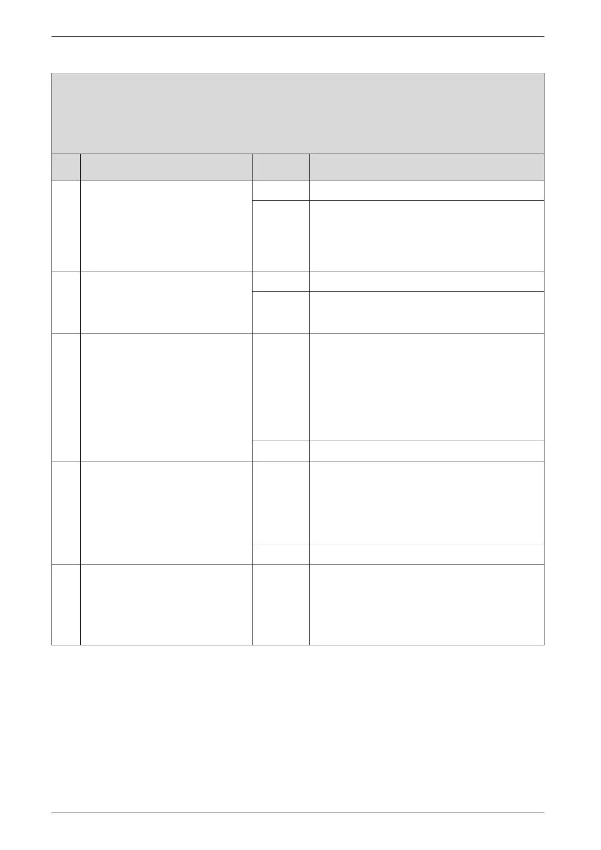
d3 flashing.
Wrong signal from pin 8-9.
Check Action
1. Jumper 8 - 9 fitted correctly? yes: ↓2.
no: B Power OFF the appliance.
B Fit jumper 8 - 9 correctly, tighten screw.
B Turn ON the appliance.
d3? ↓2.
2. B Turn ON the appliance.
B Measure voltage between Termi-
nal 4 and Terminal 8.
24 V DC?
yes: ↓3.
no: ↓5.
3. Heat store NTC sensor connected to
terminals 7, 8 and 9?
yes: B Power OFF the appliance.
B Plug heat store NTC sensor connector into PCB
control board (303, page 46, Pos. 303). If lead
has no connector: replace heat store NTC sen-
sor.
B Turn ON the appliance.
d3? ↓4.
no: ↓4.
4. Existing heat store thermostat con-
nected to Terminals 7, 8 and 9?
yes: B Power OFF the appliance.
B Fix the additional bridge 8-9 in the right position
and close the screws.
B Turn ON the appliance.
d3? ↓5.
no: ↓5.
5. The PCB control board is damaged. B Power OFF the appliance.
B Disconnect the boiler electrical connection.
B Change PCB control board.
B Reconnect the boiler electrical connection.
B Turn ON the appliance.

 Loading...


