General Procedures / Information
FaxCentre F110 12/04 6-69
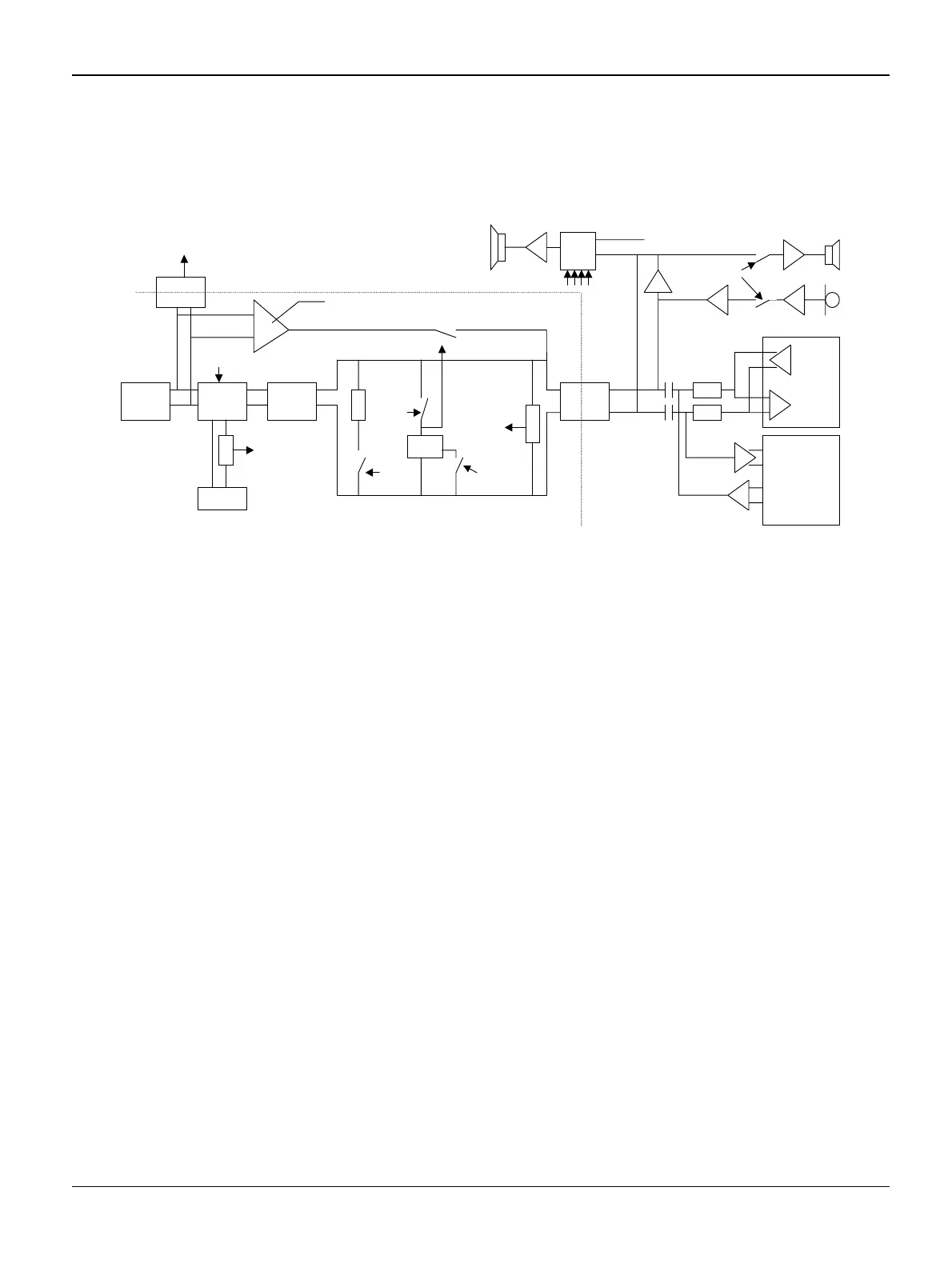
GP 34 MODEM & Line Interface
Block Diagram LIU
Figure 1 Block diagram LIU
Description
General
The direct interface to the line should be insulated from the rest of the PCB for safety reasons.
This mean than at least a free area of 3mm should be present on the layout between the hot side
and the rest of the PCB. All control signal use optocoupler with an insulation of 3000V minimum.
The AC signal is coupled to the line via a transformer with sufficient insulation.
Protection
The protection block protects the circuit against surges on the lines up to +8kV in common mode
and provides some filtering for EMC. This block should not have any effect on sinusoid signal up
to 120Vrms with an offset of 60Vdc.
1
1
Surge
Protection
Relay
Ext plug
Rin
detection
EXT_LOOP
LIU_RING
Rectifier
LIU_CLIP
DC char.
LIU_PD
LIU_CURMOD
INT_LOOP
Transfo
LIU_HOOK
ONLINE
High impedance path
Z/2
Z/2
CSP 1034
STL 7550
Mux
Tone
Vol1,
Vol2,
Vol3,
Vol_en*
Isolation
barrier
LIU_MUTE
1 0 0
0
1
0
1
0

 Loading...