Wiring Diagrams
FaxCentre F110 12/04 7-5
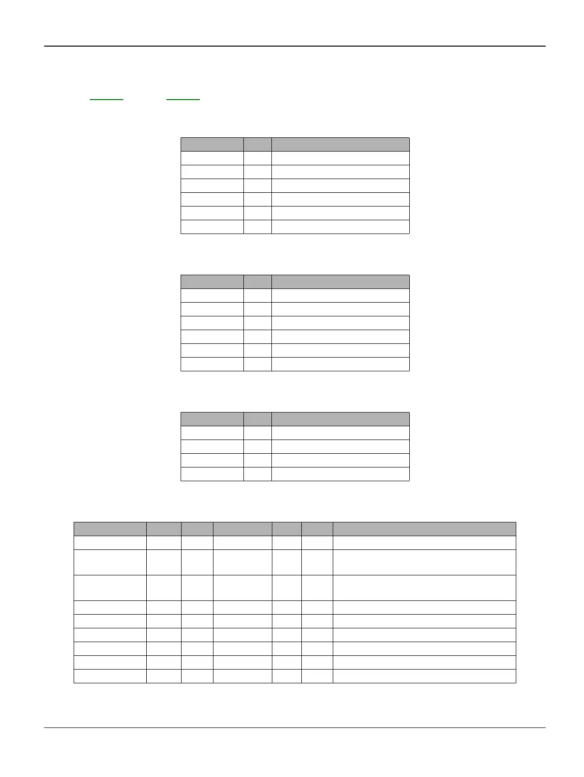
WD 3 External Connection
Refer to GP 34 through GP 44
Table 1: Line Connector P701
Name Pin Function
NC 1 Not connected
R2 2 Loopback L1
L2 3 Telephone line pair
L1 4 Telephone line pair
R1 5 Loopback L2
NC 6 Not connected
Table 2: External Phone connector P700
Name Pin Function
NC 1 Not connected
NC 2 Not connected
R2 3 Loopback L1
R1 4 Loopback L2
NC 5 Not connected
NC 6 Not connected
Table 3: Handset connector P901
Name Pin Function
MIC- 1 Microphone
GND 2 Ground (Earth)
DECT_EAR 3 Loudspeaker
MIC+ 4 Microphone
Table 4: DECT connector(P900)
Signal Pin I/O Digicolor2 Pin I/O Comment
Vcc 9 - - - - Power supply 5V
RxD 8 I USART1_T
X
145 O Serial data receive
TxD 7 O USART1_R
X
143 I Serial data transmit
-6V 6 - - - NC
DECT_RES 5 - Reset for the dect base
AGND 4 - - - Analog ground (earth)
Audio_in 3 - - - Audio in
Audio-out 2 - - - Audio out
Agnd 1 - - - Analog ground (earth)

 Loading...