General Procedures / Information
FaxCentre F110 12/04 6-71
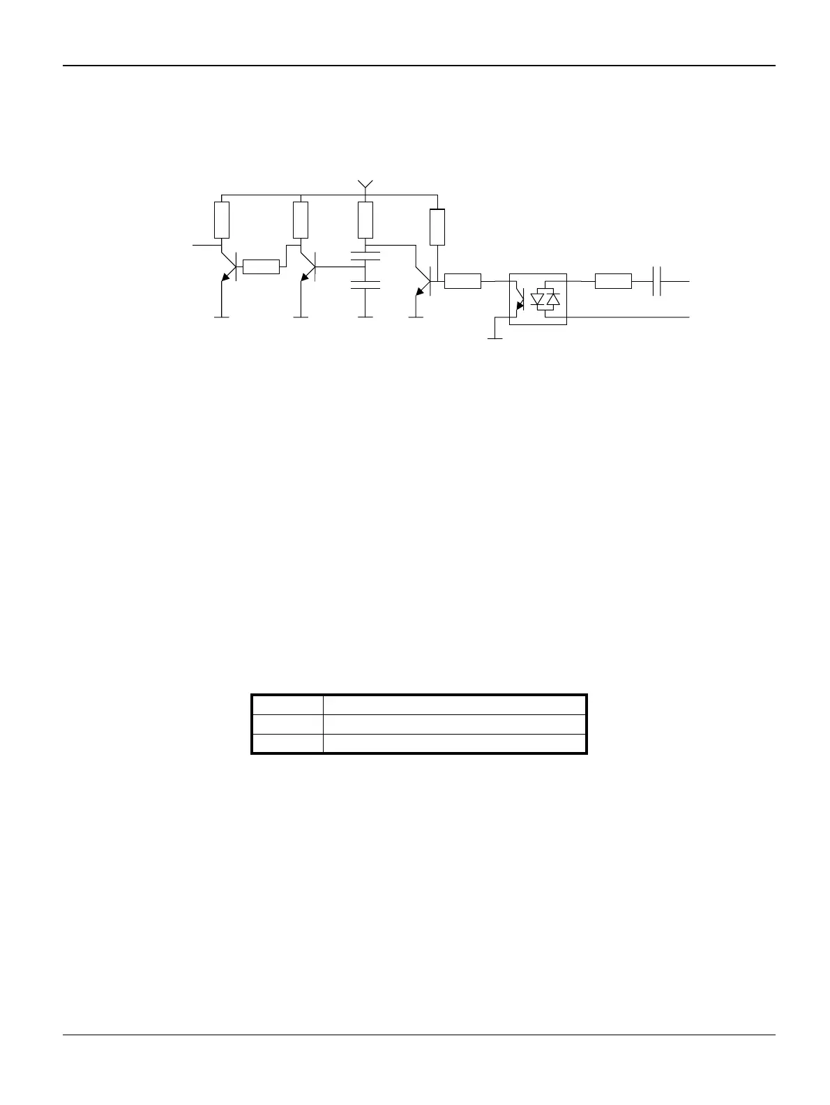
LIU_RING:
Digital InputRinger/Polarity Reversal input signal. This signal is used to detect ringer signals (fre-
quency, cadence) and polarity reversals on the line.
Figure 3
The output signal is properly provided for a ringing signal between 18Vrms and 100Vrms with a
frequency between 13Hz and 50Hz and a DC offset between –60V and +60V.
The capacitor C853 acts as high pass filter to cut off any DC current during on hook. The opto-
coupler Z850 provides a square wave signal for detecting polarity reversal and ringing signal. For
each edge the flip-flop Q851 / Q850 provides a pulse. The duration of the pulse is set with resistor
R851 and capacitor C851, C852. The transistor Q853 inverts the signal.
A square wave signal with constant pulse width (5 ms) is provided when a ring is applied. A single
pulse is provided if the line has been reversed. The ring signal frequency is twice (x 2) the applied
ringer frequency.
Ring signal status (RING) changes if PD changes, a line break occurred or an external or parallel
phone has taken the line !
Table 1:
RING State
0 Default, no line transition occurred
1 Ring or Polarity Reversal
C853
a
b
Z850R856
R852
R851R850
C852
C851
LIU_RING
R853
R854
Q851
Q850
Q853
R858

 Loading...