Disassembly
5-10
5.9 Engine Shield Assembly and Exit Board
1. Remove the rear cover, see "5.4 Rear Cover" on page 5-5.
2. Remove the top cover, see "5.5 Top Cover" on page 5-6.
3. Remove the right cover, see "5.7 Side Cover (Left and Right)" on page 5-8.
4. Remove the paper tray.
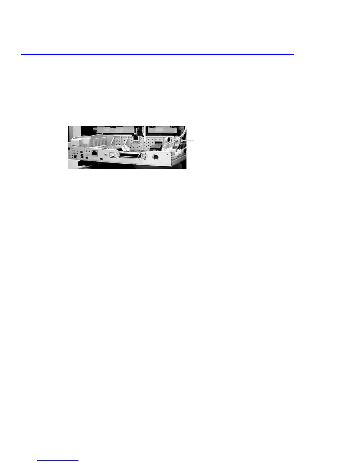
5. Remove 1 screw securing the SMPS shield and remove the shield.
6. Disconnect the following wiring harnesses from the SMPS; on the right side printer, the fan (CN3) and the
control panel (CN4). On the rear of the printer disconnect the fuser (CN1) and exit sensor (CN6).
7. Disconnect the following wiring harnesses connected to the main board.
Caution
Be sure all 12 wiring harnesses are diconnected from the assembly.
Caution
In the next step you will be turning the printer over, use caution when working on the printer in
order to avoid damaging the exit rollers.
CN 5 Laser Unit CN 10 Manual Solenoid
CN 6 Motor CN 11 PTL
CN 8 Pickup Sol CN 17 MP sensor
CN 9 Regi Sol CN 18 CRUM
Shield
Scre
 Loading...