FMC XM105 Debug Card User Guide www.xilinx.com 21
UG537 (v1.2) September 24, 2010
Board Technical Description
7. Connector J15
This 6-position connector provides an interface from the XM105 to four single-ended
signals on the board’s FMC LPC or FMC HPC interface. Connections between the
mezzanine FMC HPC and connector J15 are defined in Table 1-8. These four FMC LPC
signals are connected to green LEDS on the XM105.
8. User LEDS
Four green user LEDS are provided on the XM105, with reference designators as shown in
Table 1-8. LEDS are illuminated with an active-High signal from the FPGA on the board.
9. Connector J2
This 40-position connector provides an interface from the XM105 to 40 single-ended
signals on the board’s FMC HPC interface. Connections between the mezzanine FMC HPC
and connector J2 are defined in Table 1-9, This interface can only be utilized when installed
in a board supporting the FMC HPC interface.
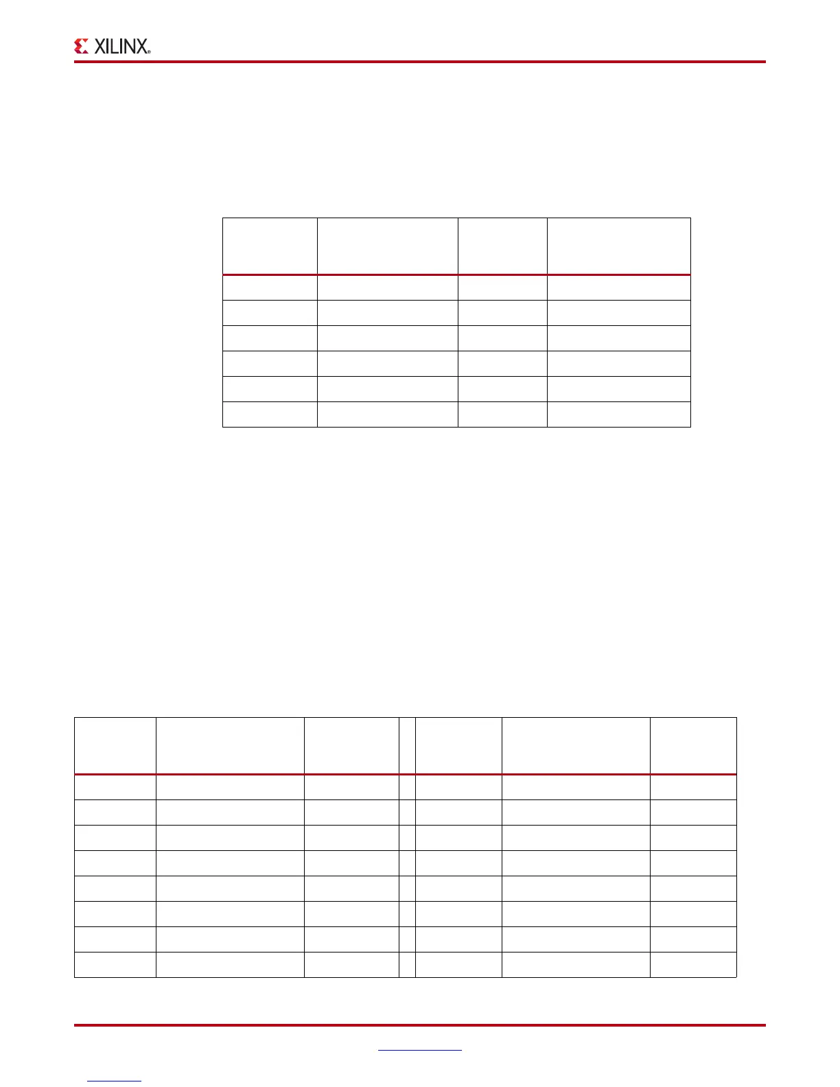
Table 1-8: Mezzanine FMC J17 to Connector J15 Pin Assignments
FMC HPC
Connector J17
Pin
Signal Name
J15
Connector
(Odd Pins)
User LED Reference
Designator Silk
Screen
– VADJ1 –
– GROUND2 –
H37 FMC_LA32_P
(1)
3DS4
H38 FMC_LA32_N
(1)
4DS3
G36 FMC_LA33_P
(1)
5DS2
G37 FMC_LA33_N
(1)
6DS1
Notes:
1. These signals are also connected to the anode of green LEDS. The LED cathodes are
connected to 27.4 ohm resistors to ground.
Table 1-9: Mezzanine FMC HPC J17 to Connector J2 Pin Assignments
FMC HPC
Connector
J17 Pin
Signal Name
J2 Connector
(Odd Pins)
FMC HPC
Connector
J17 Pin
Signal Name
J2
Connector
(Even Pins)
K25 FMC_HB00_CC _P
(1)
1 K31 FMC_HB10_P 2
K26 FMC_HB00_CC _N
(1)
3 K32 FMC_HB10_N 4
J24 FMC_HB01_P 5 J30 FMC_HB11_P 6
J25 FMC_HB01_N 7 J31 FMC_HB11_N 8
F22 FMC_HB02_P 9 F31 FMC_HB12_P 10
F23 FMC_HB02_N 11 F32 FMC_HB12_N 12
E21 FMC_HB03_P 13 E30 FMC_HB13_P 14
E22 FMC_HB03_N 15 E31 FMC_HB13_N 16
Downloaded from Elcodis.com electronic components distributor

 Loading...


