26 www.xilinx.com FMC XM105 Debug Card User Guide
UG537 (v1.2) September 24, 2010
Chapter 1: XM105
13. Connector J19
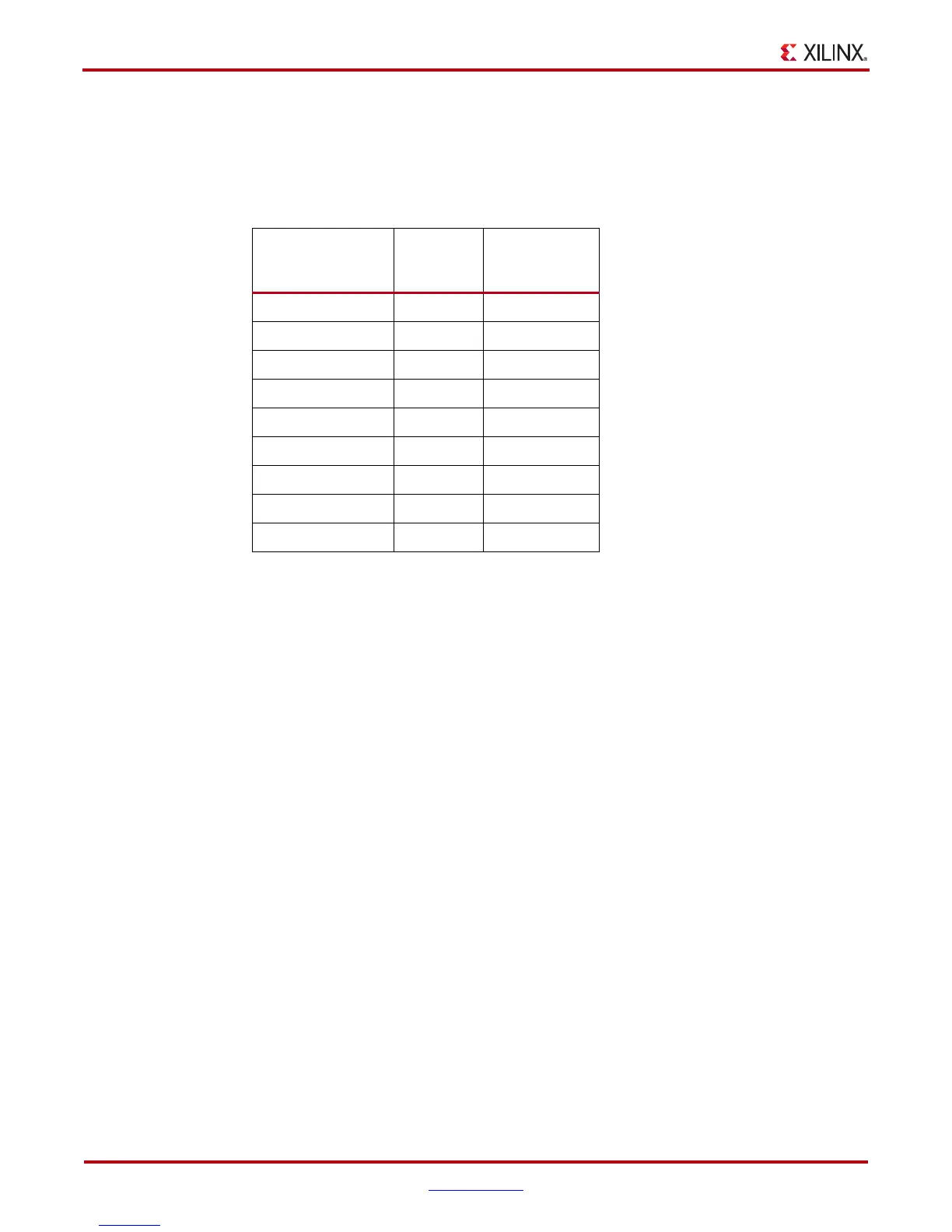
This 9-position connector (Table 1-13) does not have an interface to the FMC LPC or FMC
HPC interface of the board. It provides a connection to Mictor connector P1 and includes
3.3V and GROUND connections.
Table 1-13: Connector J19 Pin Assignments
Signal Name
J19
Connector
Pin
Mictor P1
Connector
Pin
3.3V 1 –
GROUND 2 –
NC 3 –
MICTOR_TCK 4 15
NC 5 –
MICTOR_TDO 6 11
MICTOR_TDI 7 19
NC 8 –
MICTOR_TMS 9 17
Downloaded from Elcodis.com electronic components distributor