FMC XM105 Debug Card User Guide www.xilinx.com 11
UG537 (v1.2) September 24, 2010
Board Technical Description
Detailed Description
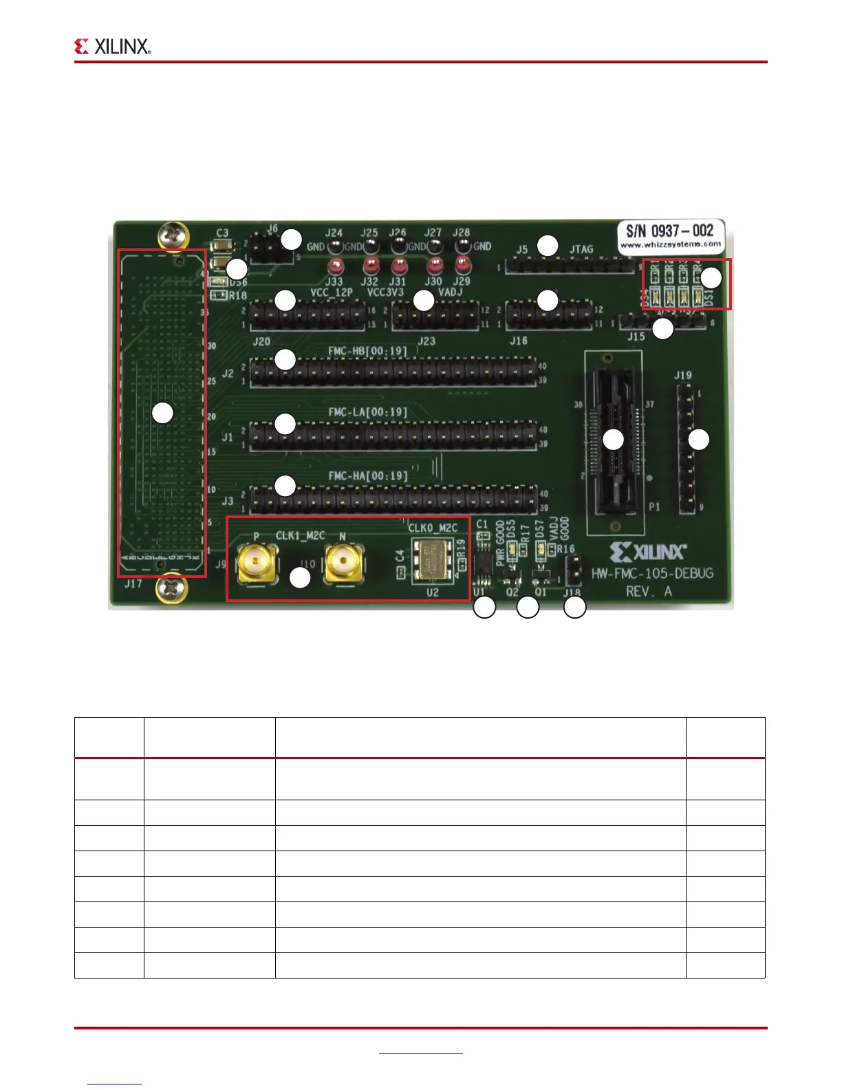
The numbered features in Figure 1-3 correlate to the features and notes listed in Table 1-2.
The XM105 can be installed on a board FMC connector supporting either low pin count or
high pin count interfaces. For LPC board applications, the HPC features are not available.
All features are available for HPC board applications.
X-Ref Target - Figure 1-3
Figure 1-3: XM105
UG537_03_102309
13
7
1
2
3
64
8
11
5
9
10
16
12
14
15
1716
Table 1-2: XM105 Features
Number Feature Notes
Schematic
Page
1
VITA 57.1 FMC HPC
connector
J17: Single-ended signals from the board, clocks, JTAG, power. This
connector is mounted on the bottom side of the board.
2-5
26-pin header J6: 3 pin x 2 row male header 7
39-pin header J5: 9 pin x 1 row male header with FMC JTAG connections 7
4 16-pin header J20: 8 pin x 2 row male header 7
5 12-pin header
(1)
J23: 6 pin x 2 row male header 8
6 12-pin header J16: 6 pin x 2 row male header 7
76-pin header J15: 6 pin x 1 row male header 7
8 User LEDS Four user LEDS 7
Downloaded from Elcodis.com electronic components distributor