VCU118 Board User Guide 13
UG1224 (v1.0) December 15, 2016
www.xilinx.com
Chapter 2: Board Setup and Configuration
24
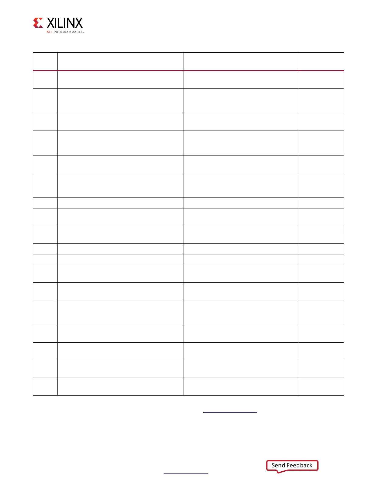
User GPIO LEDs (DS6-DS10, DS12, DS13,
DS18)
GPIO LEDs, green 0603 Lumex
SML-LX0603GW-TR
55
25
User Pushbuttons, (SW10, SW17, SW9, SW6,
SW7), CPU reset pushbutton (SW5) all
active-High
E-Switch TL3301EF100QG (north, south,
east, west, center pattern)
55
26
GPIO DIP Switch, GPIO DIP switch (SW12)
(bottom)
4-pole CTS 218-4LPSTRF 55
27
Program_B Pushbutton Switch, program_B
pushbutton switch, FPGA PROG pushbutton
(SW4)
E-Switch TL3301EF100QG 55
28
VCU118 XC7Z010 system controller, mode
switch DIP, switch (SW15)
4-pole CTS 218-4LPSTRF 49
29
User Pmod GPIO Headers, (J52 right-angle
receptacle, J53 male pin header) (top) with
level shifters (U41,U42) (bottom)
J52 Sullins PPPC062LJBN-RC,
J53 Sullins PBC36DAAN,
NXP NVT2008PW
57
30 Switches, power on/off slide switch SW1 C&K 1201M2S3AQE2 59
31
VCU118 Board Power System, power
management system (top and bottom)
Maxim MAX20751E and MAX15301
dig-ital P.O.L. controllers
60-75
32
Monitoring Voltage and Current, power
management voltage and current sensing
TI Current and Power Monitor
INA226AIDGS
60-67
33 GTY Transceivers, FMCP HSPC connector J22 Samtec ASP_184329_01 34-38
34 FMC HPC1 Connector J2 Samtec ASP_134486_01 39-42
35
Configuration Options, FPGA U1
configuration mode DIP switch, (SW16)
4-pole CTS 218-4LPSTRF 3
36
System Controller, VCU118 Zynq-7000 AP
SoC XC7Z010CLG225 (U111)
XC7Z010CLG225 46-49
37
Monitoring Voltage and Current, VCU118
board power system 2x8 shrouded PMBus
connector (J39)
ASSMAN AWHW16G-0202 59
38
Digilent USB JTAG Module, USB JTAG
module, shrouded JTAG cable connector (J3)
2x7 2 mm Molex 87832-1420 24
39
Power On/Off Slide Switch SW1, power input
connector (J15)
2x6 Molex-39-30-1060 59
41 FireFly Connector, signal and power pair (J6)
Samtec Signal: UEC5-019-2-H-D-RA-1,
Samtec Power: UCC8-10-1-H-S-1-A
50
40
PCI Express Endpoint Connectivity, lane
width select header, (J7)
2x4 0.1 inch male header Sullins
PBC36DAAN
43
Notes:
1. The VCU118 board schematics are available for download. See the VCU118 Evaluation Kit.
2. The VCU118 board jumper header locations are shown in Figure 2-2.
Table 2-1: VCU118 Board Component Descriptions (Cont’d)
Callout Feature Notes
Schematic
Page Number