ipVG Product Guide HeiTel by Xtralis
22 29794_00
6.2 Control Inputs, Error Relay, Tamper Protection
Control inputs
l Depending on control input function and on device configuration, events can be triggered by active switch
normally open, active switch normally closed, edge control, or permanent contact
In addition, ipVG has the resistance-monitored triggers Normally terminated (10k), refer to "Wiring
Variants for Voltage-monitored Control Inputs" on page 23, and Normally closed BS 8418, refer to "Wiring
Variants for Voltage-monitored Control Inputs" on page 23.
l
In principle, control inputs must be switched to ground. Use the ground terminals labelled on the
device, or the ground terminals of the terminal block labelled common ground for all inputs of type control
input" in the table above.
l Status changes at the control inputs - closing and opening of the contact - must have a duration of at least
500 ms to allow for positive detection by the device and distinction from "swish contacts".
Error relay
l The device configuration allows designation of the integrated relay as error relay in order to report certain
operating states or malfunctions using dry contacts.
For a detailed list of error messages that can trigger the error relay, refer to chapter "Logfile", refer to "Logfile
command overview" on page42. Viewing the Logfile automatically causes reset of the error message; the
error relay is de-energised. Refer to the guide of the respective CamControl software for more information on
logfile configuration and evaluation.
The ipVG video system does not have an error LED. The error is only indicated in the CamControl LITE or
CamControl PRO software.
Tamper protection
The error relay is pulled in idle - no error. Therefore the error relay can be used as tamper detector, as it
automatically falls off in the event of power failure (e.g. caused by cut power lines). Depending on the error
relay wiring, an interruption of the relay line itself can be reported as well.
Note: There is a possibility that tamper protection will not work if error relay switching is not consistent
with the operating mode.
6.2.1 Specification of the Control Inputs
Standard Switching for Control Inputs
The ipVG has a number of control inputs (Al a/d, Control IN1-IN6, Tamper).
Depending on the configuration, these can be activated by "Normally closed" or "Normally opened" contacts.
Note: The control inputs must always be activated such that they are potential-free.
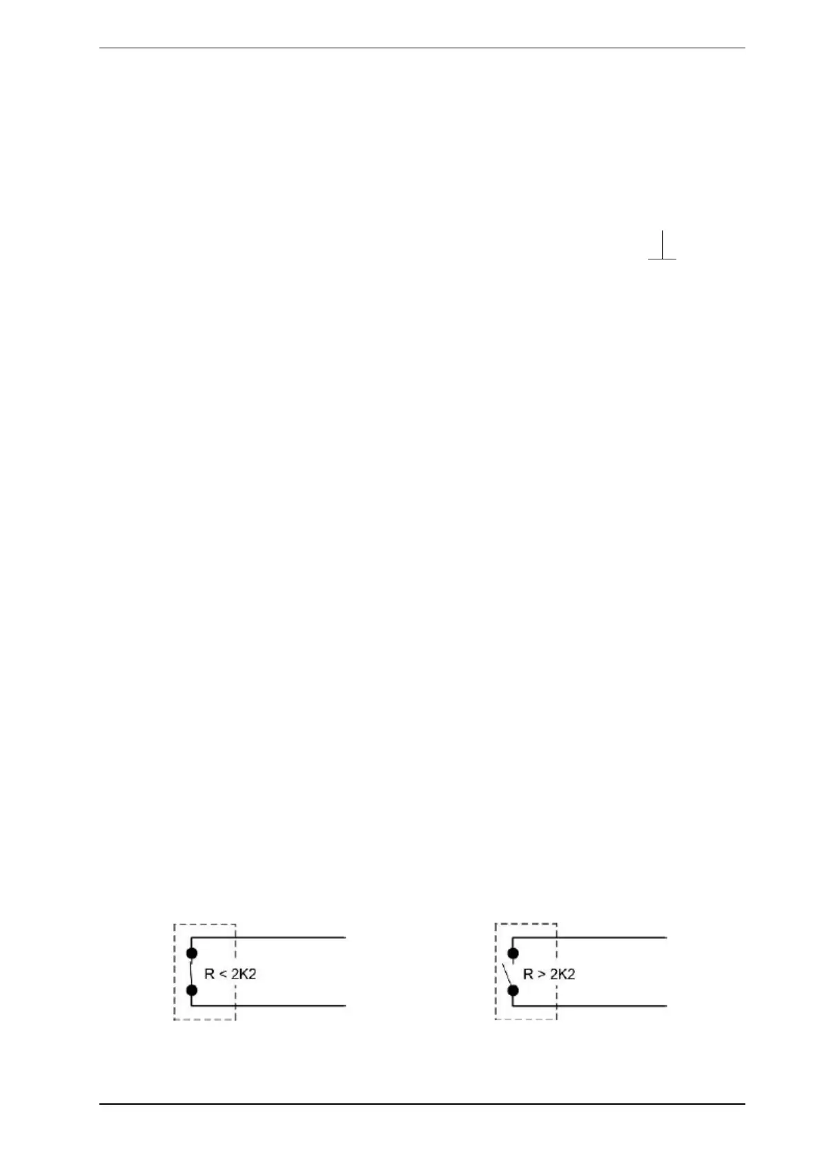
Input circuits of control inputs
Activation with "Normally closed" Activation with "Normally opened"
 Loading...