HeiTel by Xtralis ipVG Product Guide
29794_00 23
Wiring Variants for Voltage-monitored Control Inputs
In addition to standard wiring of control inputs, the ipVG permits different types of voltage monitoring.
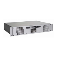
Normally terminated
The wiring variant Normally terminated allows different circuitry for "Normally opened" and "Normally closed".
For circuitry with a resistance, a distinction is made between two different states:
l Not triggered: The figures show the safe state in each case (not triggered) of the detector line or the
control input for the variants "Normally opened" and "Normally closed".
l Camera alarm: If the "Normally opened" or "Normally closed" contact is operated, depending on the type
of circuit, a camera alarm is activated. Manipulations of the detector line such as interruption or short
circuit cause triggering as soon as the ipVG no longer measures the predefined control resistance of 10
kOhm (±40%).
Normally closed BS 8418
In the wiring variant Normally closed BS 8418 with two resistances a distinction is made between three
different states:
l Not triggered: The figure shows the safe state (not triggered) of the detector line or the control input.
l Camera alarm: If the "Normally closed" contact is operated, a camera alarm is activated.
l Sabotage alarm: If the detector line is interrupted or shorted, a sabotage alarm is activated.
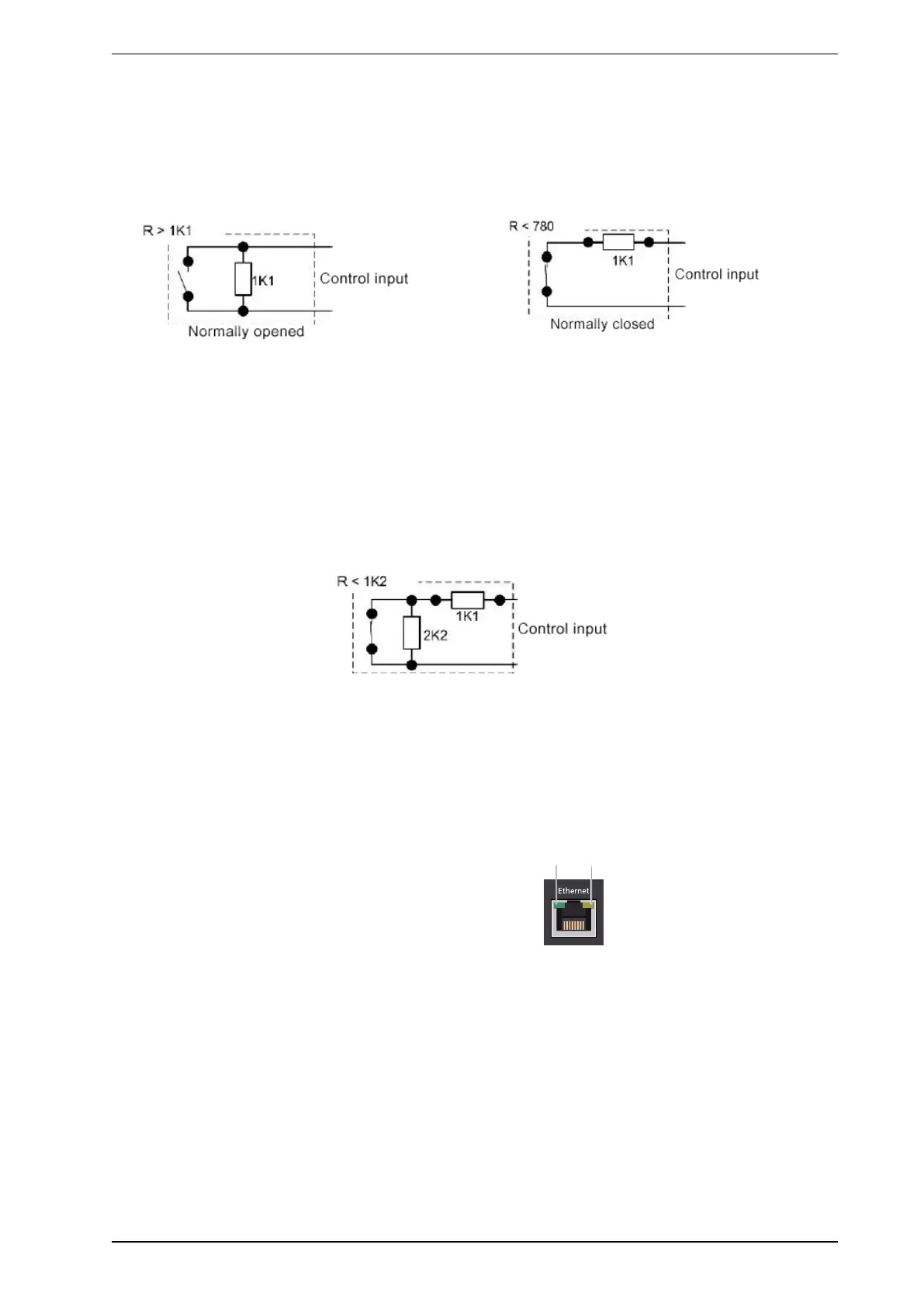
6.3 Ethernet Interface
l ACT: Flashes at data transmissions
l Link: Lights up when the network is connected correctly
 Loading...